SmartPAC PRO User Manual
1143100
Chapter 2 – Installing SmartPAC PRO
67
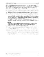
To mount the ProCamPAC Output Assembly and wire it to the ProCamPAC board inside the
SmartPAC PRO control, follow the instructions below. These instructions may be used with either the
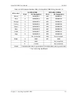
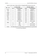
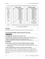
8- or 16-channel ProCamPAC board. Refer to Table 2-8 and Table 2-9 for wiring connections. A
wiring diagram is provided in Figure 3 at the end of the manual.
1.
Select a convenient location for running conduit from the ProCamPAC Output Assembly to the
equipment that it will control.
2.
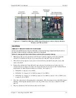
Mount the output enclosure, using the mounting holes on the flanges as shown in Figure 2-14.
3.
Select the relays to be used with each channel. Relays should already be plugged into the Cam
Outputs board (see Figure 2-14), each relay labelled with its type (i.e., standard or solid state).
Standard relays can be plugged only into the slots labeled K301 through K305, K307, K309, and
K311, which are channels 1-8. Optional solid state relays can be plugged only into slots labeled
K306, K308, K310, and K312, which are channels 5-8.
Locate the 12-conductor cable(s) for wiring the ProCamPAC board solid state relay into
channel 5 (location K306), you cannot plug a standard relay into location K305. See Figure 2-14.
Example
Say you wish to use three standard relays and one solid state relay. You would install the
three standard relays in channels 1 through 3, and the solid state relay in channel 5,
skipping the channel 4 output for all wiring and programming.
4.
To remove a relay, pull the plastic retention clip away from the relay and pull the relay straight
out of its socket. When re-inserting the relay, make sure that the pins line up with the socket
holes, then press in firmly.
5.
Locate the 12-conductor cable(s) for wiring the ProCamPAC board (see Figure 2-14 for layouts
of 8- and 16-channel boards) to terminal block TB301 inside the ProCamPAC Output enclosure.
If you are wiring an 8-channel ProCamPAC, one cable is supplied (for channels 1-8). If you are
wiring a 16-channel board, two cables are supplied, one for channels 1 through 8, the other for
channels 9 through 16.
Summary of Contents for SmartPAC PRO
Page 1: ......
Page 2: ......
Page 4: ......
Page 6: ......
Page 20: ......
Page 22: ......
Page 24: ......
Page 42: ...1143100 SmartPAC PRO User Manual 42 Chapter 1 Introduction to SmartPAC PRO ...
Page 142: ...1143100 SmartPAC PRO User Manual 142 Chapter 4 SmartPAC PRO Program Mode ...
Page 200: ...1143100 SmartPAC PRO User Manual 200 Chapter 6 Using DiProPAC Die Protection Optional ...
Page 222: ...1143100 SmartPAC PRO User Manual 222 Chapter 7 ProCamPAC Instructions ...
Page 254: ...1143100 SmartPAC PRO User Manual Appendix C SmartView Remote Viewing and E mail Setup 254 ...
Page 280: ...SmartPAC PRO User Manual 1143100 280 Appendix C Reporting Downtime and Scrap to SFC ...
Page 290: ...SmartPAC PRO User Manual 1143100 290 Index Y yellow fault 232 yellow sensor 169 ...
Page 292: ......
Page 294: ......
Page 296: ......
Page 298: ......
Page 300: ......
Page 301: ......
Page 302: ......
Page 303: ......
Page 304: ......
Page 305: ......
Page 306: ......
Page 307: ......
Page 308: ......
Page 309: ......
Page 310: ......
Page 311: ......
Page 312: ......
Page 313: ......
Page 314: ......
Page 315: ......
Page 316: ......
Page 317: ......
Page 318: ......


