


VIP 110-24
Operator’s Manual (rev E)
- 32 -
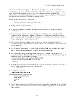
8.
Move the Ethernet cable from the repeater power inserter to the power inserter connected to the
root radio. At the DOS window invoke once again the Econsole program. Configure the second
radio (defined as the “root”) by typing the commands:
> load factory
>
node type=root
> save-configuration
9.
Once a radio is configured as the root it will establish a RF communication with the second radio.
To verify this connection type:
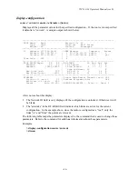
> show radio-node
Verify that the two radios are listed with the correct serial numbers. The output also displays the
transmit RF power and Receive Signal Strength (RSSI) in both link directions.
10.
Once the link is established, Econsole can be used to configure the local or the remote radio. In
order to switch the Econsole connection, logout of the current connection and re-invoke
Econsole:
> logout
> econ
Econsole will list the two radios and give a choice to connect to either. Section 6 describes the
command language used to further modify the radio’s operating parameters.
5.2
Bench Check Out (using radio auxiliary ports)
1.
Connect each
VIP 110-24
Auxiliary Port to a terminal, or a PC running a terminal emulation
program. Configure the terminal settings as follows:
Baud rate: 9600
Word length: 8 bits
Parity: none
Stop bits: 1
2.
Connect each Power Inserter Unit to the respective
VIP 110-24
using a CAT 5 cable as defined in
section 2.
3.
At the root radio connect the radio Antenna B port (N type connector) to an appropriate 2.4 GHz
band antenna using an RF coaxial cable.
4.
At the repeater radio connect the radio Antenna A port to an appropriate 2.4 GHz band antenna
using an RF coaxial cable.
5.
Connect the two Power Inserter Units to a power outlet. Make sure that the power supplies are
rated for the appropriate voltage (110 or 220 Vac).
6.
The radios will perform power up calibration and diagnostic tests. Verify that radios identify
themselves with the correct serial number. At the end of the tests, the radios output the command
prompt:
ucw-nnnnn #>
where nnnnn are the last five digits of the radio serial number.
Summary of Contents for VIP 110-24
Page 2: ......
Page 5: ...VIP 110 24 Operator s Manual rev E iv...
Page 37: ...VIP 110 24 Operator s Manual rev E 30...
Page 73: ...VIP 110 24 Operator s Manual rev E 66...
Page 89: ...VIP 110 24 Operator s Manual rev E 82...
Page 91: ...VIP 110 24 Operator s Manual rev E 84...


