


VIP 110-24
Operator’s Manual (rev E)
- 7 -
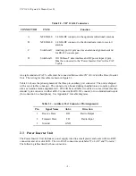
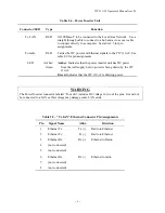
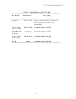
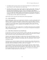
Table 2.6 – “To radio” Ethernet Connector Pin Assignments
Pin
Signal Name
Abbr.
Direction
1
Ethernet Tx
Tx (+)
Radio to Ethernet
2
Ethernet Tx
Tx (-)
Radio to Ethernet
3
Ethernet Rx
Rx (+)
Ethernet to Radio
4
+18 VDC
DCV (+)
Power Inserter to Radio
5
+18 VDC
DCV(+)
Power Inserter to Radio
6
Ethernet Rx
Rx (-)
Ethernet to Radio
7
18 VDC ground
GND(-)
Power Inserter to Radio
8
18 VDC ground
GND(-)
Power Inserter to Radio
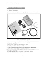
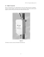
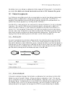
2.4
Outdoor Interconnect Cable
The interconnect cable between the Power Inserter Unit and the
VIP 110-24
carries the following
signals
1.
DC voltage to supply power to the
VIP 110-24
.
2.
10 Base-T Ethernet data.
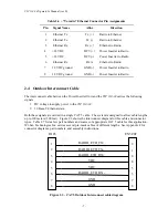
Both these signals are carried in a single CAT 5 cable. The system is designed to allow cable lengths
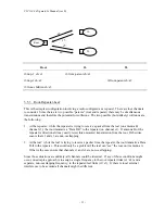
up to 100 meters (300 feet). Figure 2.3 shows the interconnect diagram for this cable and connector
types. Table 2.7 lists a few part numbers and sources of appropriate CAT 5 cable for this application.
Wi-Lan Technologies Inc. carries several pre-made cables of different lengths. See Appendix F for
connector diagrams, part numbers, and assembly instructions.
Figure 2.3 – CAT 5 Outdoor Interconnect cable diagram
RADIO
RADIO_ETH_TX-
RADIO
VDC
VDC
RADIO_ETH_RX-
GND
GND
2
1
4
6
5
3
7
8
1
2
3
4
5
6
7
8
RJ 45
EN3C8F
Summary of Contents for VIP 110-24
Page 2: ......
Page 5: ...VIP 110 24 Operator s Manual rev E iv...
Page 37: ...VIP 110 24 Operator s Manual rev E 30...
Page 73: ...VIP 110 24 Operator s Manual rev E 66...
Page 89: ...VIP 110 24 Operator s Manual rev E 82...
Page 91: ...VIP 110 24 Operator s Manual rev E 84...


