


VIP 110-24
Operator’s Manual (rev E)
- 15 -
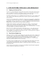
omni antenna, at the same time that leaf “3L” performs an inbound transmission to the root. If the
inbound and outbound were on the same frequency, there would be a collision at the root.
However, a transmission within any given “branch”, (defined as a parent radio together with its
“children” that are only one hop away) will not interfere with simultaneous transmissions in any other
branches. Any two simultaneous outbound transmissions in different branches will be received by the
intended nodes due to the high gain antennas attached to port “A” of the downstream radios.
Likewise, any two simultaneous inbound transmissions in different branches will be received by the
intended upstream nodes due to the high gain of the antenna A pointed directly at the upstream radio.
This scheme is further optimized by setting the transmit power in every link to achieve no more than
the adequate link margin for that particular link.
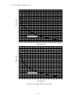
There may be specific situations where the diversity achieved through the dual frequency operation
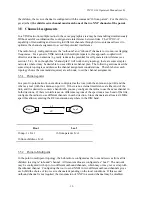
and antenna directivity would not work. For example, if radios 1R, 1.2R, and 1.2.2L (figure 3.1)
were in a straight line, inbound transmissions from 1.2.2L could reach 1R and interfere with a
simultaneous inbound transmission from 1.1L. Those specific cases can be addressed with one or
more of the following techniques:
1.
Power management: reduce the transmit power from 1.2.2L so that the signal at 1R is
significantly below the signal from 1.1L
2.
Additional channels: Use the “primary” set of frequency channels between 1R and its children,
and the “secondary” (non-overlapping) set of channels between 1.2R and its children.
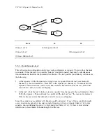
3.
Antenna polarization: use horizontal antenna polarization between 1.2R and its children, and
vertical polarization between 1R and its children.
The VINE approach to frequency diversity allows deploying a system with radios transmitting
simultaneously in the same geographic area, using only two non-overlapping channels for the entire
RF network. This should be contrasted with a cell based approach where adjacent cells are typically
allocated to different frequencies and may require four to six non-overlapping channels.
3.6
Ethernet Bridging
The
VIP 110-24
operates as an Ethernet bridge. As a bridge, the
VIP 110-24
runs in “promiscuous
mode”, i.e., it examines all the Ethernet packets that are flowing in the local LAN. Since these
Ethernet packets contain a “source” and “destination” address, the radio quickly learns the addresses
of all the “local” stations connected to the LAN (all the “source” addresses of packets flowing in the
LAN are local).
Each
VIP 110-24
in the VINE periodically transmits the information about the local Ethernet
addresses to all other radios. Therefore every
VIP 110-24
holds an Ethernet table that includes one
entry for every Ethernet address connected to any of the LANs (this table can be examined with the
“show ethernet” command).
With this information on hand, each
VIP 110-24
examines the destination address of every Ethernet
packet in the local LAN and makes one of the following decisions:
1.
If the destination address is for a “local” station, discard the packet.
2.
If the destination address is connected to a remote radio, queue that packet to be forwarded
through the appropriate RF port.
Summary of Contents for VIP 110-24
Page 2: ......
Page 5: ...VIP 110 24 Operator s Manual rev E iv...
Page 37: ...VIP 110 24 Operator s Manual rev E 30...
Page 73: ...VIP 110 24 Operator s Manual rev E 66...
Page 89: ...VIP 110 24 Operator s Manual rev E 82...
Page 91: ...VIP 110 24 Operator s Manual rev E 84...


