


VIP 110-24
Operator’s Manual (rev E)
- 22 -
maximum speed), a tradeoff analysis can be conducted before installation to determine if lowering the
data rate will allow the radio sufficient link margin to operate. A line-of-sight is required to insure
the best performance from the radio. The calculations below will allow the operator to build towers
and other mounting areas to the correct height before the antennas are installed. The calculation of
the RSS level is useful for two purposes. The first and primary purpose to calculate the theoretical
RSS level at the receive radio is to determine the link margin at the site. This information, when
coupled with the background noise measurement, will tell the operator if a link can be established and
give a reasonable “a priori” estimate of the performance of the system. In addition to this, the RSS
level allows the operator to do a quick check on the integrity of the system installation by verifying
that the received RSS level is close to the calculated value.
A background scan is easily accomplished using the built in Spectrum Analysis tool of the
VIP 110-
24
. This should be done before any installation of any equipment is completed.
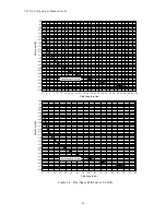
Although the graph of figure 4-1 provides a useful guide to antenna height requirements, a more
accurate determination of those requirements can be obtained by means of the analysis described in
the following steps.
NOTE
Computer programs available from many vendors can perform
portions of this procedure.
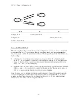
Requirements for this procedure are:
1.
A topographical map of the installation site.
2.
Graph paper, ten divisions per inch or equivalent metric scale
3.
Straight edge
4.
Calculator
Procedure:
1.
On the topographic map, lot the precise location of each antenna site.
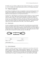
2.
Draw a line between the sites; this line is the radio path.
3.
On the graph paper, establish a vertical axis for elevation and a horizontal axis for distance. It is
usually easiest to make the vertical axis in feet or meters and the horizontal axis in miles or
kilometers.
4.
Following the radio path line on the map, identify all obstructions. Most topographical maps
identify geographic information, such as hills and lakes, only. However, vegetation, buildings or
other structures that will interfere with radio transmissions must also be included.
5.
Plot each obstruction on the graph, marking its elevation and distance from the sites. For dense
vegetation such as forests, add 40 to 60 feet (12 to 18 m) to the ground elevation.
Summary of Contents for VIP 110-24
Page 2: ......
Page 5: ...VIP 110 24 Operator s Manual rev E iv...
Page 37: ...VIP 110 24 Operator s Manual rev E 30...
Page 73: ...VIP 110 24 Operator s Manual rev E 66...
Page 89: ...VIP 110 24 Operator s Manual rev E 82...
Page 91: ...VIP 110 24 Operator s Manual rev E 84...


