


VIP 110-24
Operator’s Manual (rev E)
- 20 -
3.
All antennas must be properly oriented, and a directional antenna must be carefully aimed at its
target antenna to ensure communication at maximum range.
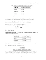
4.
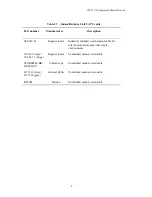
All antenna cables attenuate (reduce) signal strength in proportion to their length. Therefore, the
distance between the antenna and the radio is limited to a cable length that does not exceed the
maximum attenuation tolerated by the system. Since various cable types offer different
attenuation levels, maximum length depends on cable type. Generally speaking, because the
VIP
110-24
is an outdoor unit with the output port connected directly to the antenna, cable losses are
negligible and the radio will compensate, but there are limits to this compensation. See table 4-2
for sample cables and their respective attenuation values.
Each of these criteria is discussed at greater length in the following paragraphs.
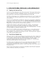
4.3.1
Line-of-Sight Path
Because high-frequency radio waves are attenuated by obstructions, a clear line-of-sight path between
antennas is required for optimum performance at maximum range. For shorter ranges, a degree of
obstruction may be acceptable. For example, at less than maximum ranges the radio has some ability
to “penetrate” trees and other foliage. On the other hand, geographical features (hills) and large
buildings are likely to interfere with communications, and antennas must be elevated to “see” each
other above such objects.
Because of the uncertainties of radio communication, it is difficult to predict the results in conditions
where obstructions exist. The only valid advice is to try the proposed configuration and be prepared
to move or elevate the antennas.
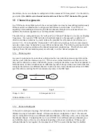
4.3.2
Radio Horizon (Maximum Line-of-Sight Range)
In visual terms, the horizon is the point in the distance where an object drops out of sight because it is
blocked by the earth’s curvature. If the observer or object is elevated, the visual horizon is extended,
that is, the object can be seen at a greater distance before it drops out of view.
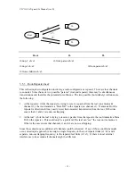
The same concept applies to radio signals: The radio horizon is the point in the distance where the
path between two antennas is blocked by the curvature of the earth. Like the visual horizon, the radio
horizon can be extended by elevating the transmitting antenna, receiving antenna, or both to extend
communication range.
The radio horizon can also be extended or shortened by certain phenomena such as refraction due to
atmospheric density and temperature inversions. Fog and rain, which reduce signal strength, can also
shorten the radio horizon although in the ISM band, this loss is negligible.
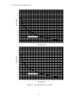
A reasonable approximation of the radio horizon based on antenna height can be obtained from the
graph in figure 4-1. (Note that this graph does not take atmospheric effects into account.) To use the
graph, set a straight edge so that it crosses the height of one of the antennas in the column on the left
and the height of the other antenna in the column on the right. The radio horizon in miles/km is
shown where the straight edge crosses the center column.
Summary of Contents for VIP 110-24
Page 2: ......
Page 5: ...VIP 110 24 Operator s Manual rev E iv...
Page 37: ...VIP 110 24 Operator s Manual rev E 30...
Page 73: ...VIP 110 24 Operator s Manual rev E 66...
Page 89: ...VIP 110 24 Operator s Manual rev E 82...
Page 91: ...VIP 110 24 Operator s Manual rev E 84...


