


VIP 110-24
Operator’s Manual (rev E)
- 5 -
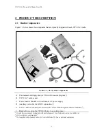
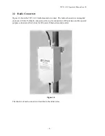
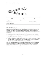
Table 2.2 – VIP 110-24 Connectors
CONNECTOR
TYPE
Function
A
N-FEMALE
2.4 GHz RF connector to the upstream (directional) antenna
B
N-FEMALE
2.4 GHz RF connector to the downstream (omni or sector)
antenna
C
Switchcraft
Auxiliary port (3 pin) used as an antenna alignment aid
and
for RS-232 console port.
D
Switchcraft
10/100 Base-T data interface and DC power input (8 pin).
Must be connected to the “Power Inserter Unit” with a CAT
5 cable.
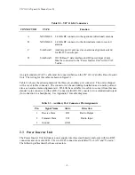
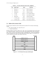
An eight conductor CAT 5 cable must be connected between the
VIP 110-24
and the Power Inserter
Unit. The wiring for this cable is shown in figure 2.3.
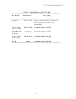
Table 2.3 shows the pin assignment of the three pin, auxiliary port connector. The unit is shipped
with a cover in this connector. The connector can be used during installation as a console port and
also as an audio antenna alignment aid. Wi-LAN has available two cables to convert from this non-
standar 3-pin connector to either a DE-9 connector (for RS-232 console) or to a standard audio jack
(for connection to a headphone). See Appendix F for cable diagrams.
Table 2.3 – Auxiliary Port Connector Pin Assignments
Pin
Signal Name
Abbr.
Direction
1
Receive Data
RD
Radio Output
2
Transmit Data
TD
Radio Input
3
Ground
GND
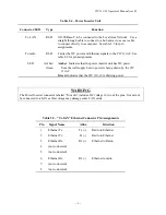
2.3
Power Inserter Unit
The Power Inserter Unit includes a power supply wired to a small plastic enclosure with two RJ45
connectors and a bi-color LED. The two RJ-45 connectors are labeled “To LAN” and “To radio”.
The following tables describe those connectors.
Summary of Contents for VIP 110-24
Page 2: ......
Page 5: ...VIP 110 24 Operator s Manual rev E iv...
Page 37: ...VIP 110 24 Operator s Manual rev E 30...
Page 73: ...VIP 110 24 Operator s Manual rev E 66...
Page 89: ...VIP 110 24 Operator s Manual rev E 82...
Page 91: ...VIP 110 24 Operator s Manual rev E 84...


