background image

4-21

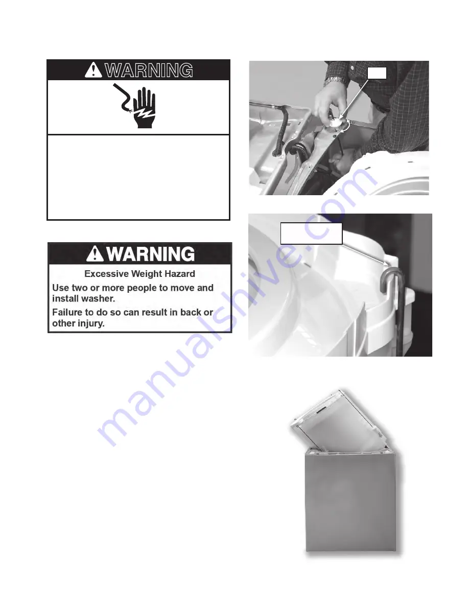
Figure 3

REMOVING THE TUB

Electrical Shock Hazard

Disconnect power before servicing.
Replace all parts and panels before    

operating.
Failure to do so can result in death or 

electrical shock.

WARNING

1.   Unplug washer or disconnect power.

Figure 1

Figure 2

  Ball

Hang Suspension 

Rod Here

2.   Turn off the water supply to the washer.

3.   Raise the top on the hinges. See the  


section: “REMOVING THE TOP”.

4.   Remove harness from control and water  


valves to set the top aside.

5.  Remove the basket. See the section  


REMOVING THE IMPELLER BOLT AND  


BASKET.

6.   Remove suspension rods from balls, see  


figure 1.

11.  Hang the rods on the top edge of the 


tub ring.

12.  Lift tub out, see figure 3.

Summary of Contents for Cabrio WTW5700XW

Page 1: ...TECHNICAL EDUCATION JOB AID W10329932 L 84 Vertical Modular Washer MVWC400XW MVWX500XW MVWX550XW MVWX600XW MVWX700XW WTW4950XW WTW5500XW WTW5550XW WTW5600XW WTW5700XW ...

Page 2: ...her The Wiring Diagram used in this Job Aid is typical and should be used for training purposes only Always use the Wiring Diagram supplied with the product when servicing the washer GOALS AND OBJECTIVES The goal of this Job Aid is to provide information that will enable the In Home Service Professional to properly diagnose malfunctions and repair the Vertical Modular Washer The objectives of this...

Page 3: ...Washer 3 9 Using Laundry Product Dispensers 3 10 Troubleshooting 3 14 COMPONENT ACCESS 4 1 Component Locations 4 1 4 2 Removing The Control Panel 4 3 Removing The Control 4 4 User Interface Removal And Installation Procedure 4 5 Removing The Top 4 6 Removing The Water Inlet Valve 4 7 Removing The Detergent Dispenser Assembly 4 8 Removing The Lid Switch Lock Assembly 4 9 Removing The Lid Strike On ...

Page 4: ...ued TESTING 5 1 Activating The Service Diagnostic Modes 5 2 Diagnostic Guide 5 3 Fault Code Display Mode 5 3 Automatic Test Mode 5 4 Manual Test Mode 5 4 Calibration Mode 5 4 Sales Demo Mode 5 4 UI Test Mode 5 5 Software Version Display Mode 5 5 Customer Viewable Fault Codes 5 5 Automatic Test Mode 5 8 Manual Test Mode 5 9 ...

Page 5: ...ructions WARNING DANGER IMPORTANT Electrostatic Discharge ESD Sensitive Electronics ESD problems are present everywhere Most people begin to feel an ESD discharge at approximately 3000V It takes as little as 10V to destroy damage or weaken the main control assembly The new main control assembly may appear to work well after repair is finished but a malfunction may occur at a later date due to ESD s...

Page 6: ...rizontial T Top Load V Vertical W Workspace PRODUCT B Combo C Compact D Dryer P Pedestal T Thin Twin Stack W Washer SERIES 1 Innovation 2 Commercial 3 Compact 4 VMW Good Stack 5 LEAP VMW Better 6 Oasis 7 24 Front Load VMW Best 8 Mid Line Front Load 9 Duet Front Load PRICE POINT LEVELS 1 9 TRADE PARTNER ID 00 BRANDED YEAR OF INTRODUCTION X 2010 COLOR CODE A Aspen B Black C Tuscan Chestnut E Ocean S...

Page 7: ...ESS E Electric F Front Load G Gas H Horizontial T Top Load V Vertical W Workspace PRODUCT B Combo C Compact D Dryer P Pedestal T Thin Twin Stack W Washer SERIES A All Accessory B Bravos C Centennial E Epic S Stack X VMW Better Z Epic Z PRICE POINT LEVELS 1 9 TRADE PARTNER ID 00 BRANDED YEAR OF INTRODUCTION X 2010 COLOR CODE A Aspen B Black C Tuscan Chestnut E Ocean Sapphire F Classic Red K Blue L ...

Page 8: ...1 4 MODEL SERIAL NUMBER LABEL AND TECH SHEET LOCATIONS The Model Serial Number Label and Tech Sheet locations are shown below Model Serial Number Label Tech Sheet Behind Front Panel ...

Page 9: ...p Load Washer Color White Capacity Cu Ft DOE 3 7 IEC Capacity 4 3 Energy Star Tier Level 2011 2 4 MEF 4 0 WF Basket Material Stainless Steel Bleach Disp Dump Bleach Fab Sof Disp Downeyball Detergent Disp No Lid Solid Water Temps 4 Max Spin Speeds 800 Agitator or Impeller Height Impeller Unique 43 Install Depth Min Max 27 Width 26 Model Number WTW5600XW Model Description Top Load Washer Color White...

Page 10: ...less Steel Bleach Disp Dump Bleach Fab Sof Disp Downeyball Detergent Disp No Lid Solid Water Temps 4 Max Spin Speeds 800 Agitator or Impeller Height Impeller Unique 43 Install Depth Min Max 27 Width 26 Model Number MVWC600XW Model Description Top Load Washer Color White Capacity Cu Ft DOE 3 7 IEC Capacity 4 3 Energy Star Tier Level 2011 2 4 MEF 4 0 WF Basket Material Stainless Steel Bleach Disp Du...

Page 11: ...ssages in this manual and on your appliance Always read and obey all safety messages This is the safety alert symbol This symbol alerts you to potential hazards that can kill or hurt you and others All safety messages will follow the safety alert symbol and either the word DANGER or WARNING These words mean follow instructions instructions DANGER WARNING WARNING Tip Over Hazard Refrigerator is top...

Page 12: ... hose too short Kit Part Number 280131 Lint clogged drain Drain protector Part Number 367031 LOCATION REQUIREMENTS Select proper location for your washer to improve performance and minimize noise and possible washer walk Install your washer in a basement laundry room closet or recessed area 4 min 102 mm Gather required tools and parts before starting installation 42 1067 mm 27 686 mm 271 2 648 mm ...

Page 13: ... Siphon Break Kit Part Number 280129 and additional drain hose Part Number 3357090 that may be purchased separately To order please see toll free phone numbers in your Use and Care Guide Minimum siphon break 28 710 mm from bottom of washer Additional hoses may be needed Floor standpipe drain system IMPORTANT To avoid siphoning no more than 4 5 113 mm of drain hose should be inside standpipe or bel...

Page 14: ... can result in a risk of electric shock Check with a qualified electrician or serviceman if you are in doubt as to whether the appliance is properly grounded Do not modify the plug provided with the appliance if it will not fit the outlet have a proper outlet installed by a qualified electrician For a permanentl y connected washer This washer must be connected to a grounded metal permanent wiring ...

Page 15: ...e slide it over end as shown Squeeze clamp with pliers and slide black elbow end of drain hose onto black drain port and secure with clamp Attach drain hose to drain port 5 Place hose into standpipe shown in picture or over side of laundry tub IMPORTANT 4 5 113 mm of drain hose should be inside standpipe do not force excess hose into standpipe or lay on bottom of laundry tub Drain hose form must b...

Page 16: ... water may enter washer It will drain later CONNECT INLET HOSES Washer must be connected to water faucets with new inlet inlet valves If you are only connecting to a cold water faucet you must use a Y adapter not provided Attach hose to hot water faucet Screw on coupling by hand until it is seated on washer Use pliers to tighten couplings an additional two thirds turn Repeat this step with second ...

Page 17: ...nd repeat as needed HELPFUL TIP You may want to prop up front of washer about 4 102 mm with a wood block or similar object that will support weight of washer 14 Adjust leveling feet washer Use side seam as a guide to check levelness of sides Check levelness of front using lid as shown Rock washer back and forth to make sure all four feet make solid contact Not Level LEVEL Not Level 13 Check leveln...

Page 18: ... new design DRIVE SYSTEM Motor Bi directional PSC Permanent Split Capacitor 120VAC Agitation and variable spin speeds are accomplished by applying power in pulses Transmission The transmission is a non serviceable belt driven component Inner shaft top splines connect to the agitator Bottom splines connect to the splutch pulley Outer shafts top splines connect to the basket Bottom splines connect t...

Page 19: ...ough the agitator shaft The agitator al ways moves with the pulley The basket drive gear is connected to the basket by the inner splines contacting the outer splines of the transmission The cam ring raises and lowers the basket drive gear When the basket drive gear teeth are engaged to the pulley teeth the basket will spin along with the agitator ...

Page 20: ...The actuator serves several functions It has a synchronous motor that shifts the splutch slider and monitors the position of the splutch It also houses a transmission speed position optical sensor ACTUATOR ...

Page 21: ...cess during use During a cycle a lid lock mechanism will lock the lid The lid must be closed for the machine to fill wash drain or spin The mechanism houses a switch that senses that the lid is down a latch solenoid and a switch to confirm that the lid is locked LID LOCK MECHANISM ...

Page 22: ...asher provided Even in Cool wash some warm water may be added to the washer to maintain a minimum temperature SOIL LEVEL Soil level wash time is preset for each wash cycle As you press Soil Level the cycle time minutes will increase or decrease in the Estimated Time Remaining display and a dif ferent wash time will appear For most loads use the soil level that is preset with the cycle you have cho...

Page 23: ...n added for the load You may also hear water flowing through the dispenser adding deter gent to the load NOTE The sensing light may also come on during the Soak and Wash portions of the cycle This is normal DEEP CLEAN This option provides enhanced cleaning action for tough stains It will add additional time to the cycle Deep Clean should be started on a dry load only and must be selected before tu...

Page 24: ...y the selected soil level RINSE You will hear sounds similar to the wash cy cle as the washer rinses and moves the load Fabric softener will be added if the Fabric Softener option was selected SPIN The washer spins the load at increasing speeds for proper water removal based on the selected cycle and spin speed DONE Once the cycle is complete this light will come on Remove the load promptly for be...

Page 25: ...after power interruption Also use for loads that require rinsing only Drain Spin This cycle uses a high speed spin to shorten drying times for heavy fabrics or special care items Use this cycle to drain washer after cancelling a cycle or completing a cycle after a power failure NOTE Do not add detergents or bleach products when running this cycle ADDITIONAL CYCLES Soak Select Soil Level to adjust ...

Page 26: ...oad evenly See Cycle Guide for tips and more information on using the Bulky Items cycle Use garment bags to help prevent tangling when washing delicate or small items Turn knits inside out to prevent pilling Separate lint takers from lint givers Synthetics knits and corduroy fabrics will pick up lint from towels rugs and chenille fabrics Always read and follow fabric care labels instructions to av...

Page 27: ...trays 3 Add HE detergent to dispenser 5 Add fabric softener to dispenser Pour a measured amount of liquid fabric softener into tray always follow manufacturer s directions for correct amount of fabric softener based on your load size Then select Fabric Softener option IMPORTANT Fabric Softener option must be selected to ensure proper distribution at correct time in cycle fabric softener to immedia...

Page 28: ...gins Wash Temp Hot Some cold water is added to save energy This will be cooler than your hot water heater setting Warm Some cold water will be added so this will be cooler than what your previous washer provided Cool brights darks Warm water is added to assist in soil removal and to help dissolve detergents Cold Warm water may be added to assist in soil removal and to help dissolve detergents Tap ...

Page 29: ...brasive products L i q u i d c h l o r i n e b l e a c h d i s p e n s e r Replace inlet hoses after 5 years of use to reduce the risk of hose failure Periodically inspect and replace inlet hoses if bulges kinks cuts wear or leaks are found When replacing your inlet hoses mark the date of replacement on the label with a permanent marker WATER INLET HOSES 10 Select START PAUSE to begin wash cycle P...

Page 30: ...nect power 3 Run washer through BULKY ITEMS cycle to clean washer and remove antifreeze if used Use only HE recommended amount for a medium size load TRANSPORTING YOUR WASHER 1 Shut off both water faucets Disconnect and drain water inlet hoses 2 If washer will be moved during freezing weather follow WINTER STORAGE CARE directions before moving 3 Disconnect drain from drain system and drain any rem...

Page 31: ...re it to drainpipe or laundry tub Check household plumbing for leaks or clogged sink or drain Water can backup out of a clogged sink or drainpipe Check all household plumbing for leaks laundry tubs drain pipe water pipes and faucets Fill hose washers Noises It is normal to hear metal items on clothing such as metal snaps buckles or zippers touch against the stainless steel basket Objects caught in...

Page 32: ...o avoid overloading or unbalancing Not using HE detergent Only use HE detergent Suds from regular detergents can slow or stop the washer Always measure detergent and following detergent directions based on your load requirements To remove suds cancel cycle Select DRAIN SPIN Select your cycle Press START Do not add more detergent Use a cycle with a high spin speed Cycles with lower spin speeds remo...

Page 33: ...ow draining Empty pockets and use garment bags for small items Overloading or unbalanced loads will not allow the washer to spin correctly leaving the load wetter than normal See Using Your Washer for loading recommendations Washer not draining spinning loads are still wet Check plumbing for correct drain hose installation Drain hose extends into standpipe farther than 4 5 114 mm Check drain hose ...

Page 34: ...ent Run the Clean Washer cycle with AFFRESH monthly See Cleaning Your Washer in Washer Maintenance Unload washer as soon as cycle is complete Use only HE detergent Always follow the manufacturer s directions See Cleaning your Washer section Odors Empty pockets zip zippers and snap or hook fasteners before washing to avoid snags and tears Sharp items were in pockets during wash cycle Strings and st...

Page 35: ...rforming as expected cont Energy saving controlled wash temperatures Are hot and cold inlet hoses reversed inlet valve Both hot and cold water faucets must be on Inlet valve screens on washer maybe clogged Remove any kinks in the inlet hose Not using HE detergent The suds from regular detergent can prevent washer from operating correctly Use only HE detergent Always measure detergent and follow de...

Page 36: ...ay result in residual powder in the dispenser To avoid select a warmer wash temperature if possible depending on your load Use only liquid chlorine bleach in the bleach dispenser Incorrect dispenser operation First try the solutions suggested here or visit our website at www whirlpool com help for assistance and to possibly avoid a service call Washer not performing as expected cont Button sounds ...

Page 37: ...ar Washer The components and their locations are shown Water Valves Panel Clips User Interface Thermistor Front of washer Control Electrical Shock Hazard Disconnect power before servicing Replace all parts and panels before operating Failure to do so can result in death or electrical shock WARNING Unplug washer or disconnect power ...

Page 38: ...enser Assembly View from the front with the top lifted View from the bottom with the washer on it s back with pulley cover removed Suspension Spring Capacitor Motor Belt Splutch Pulley Counter Balance Drain Pump Motor Drain Pump Motor Hose Tub Assembly Wire Harness Wire Harness Shifter ...

Page 39: ...power before servicing Replace all parts and panels before operating Failure to do so can result in death or electrical shock WARNING 4 Push back on the control panel just enough to slide a putty knife under the right or left corner of the control panel Lift the corner of the panel and push in with the putty knife blade to release the clip Repeat the procedure for the other clip see figures 2 and ...

Page 40: ...abs back for J 2 removal b Pull tabs back for J 12 removal c Remove two wire connector at J 7 d Wires for J 3 are routed and tucked under the braces and are held in place by a tree clip Remove the connector by pinching the tabs on the sides of the connector e J 15 and J 16 are pinch connectors and the wires are held by a tree clip Figure 1 5 Remove the knob by grasping it and pulling it toward you...

Page 41: ...ure 1 Figure 2 Figure 3 IMPORTANT Electrostatic Discharge ESD Sensitive Electronics ESD problems are present everywhere ESD may damage or weaken the machine control electron ics The new control assembly may appear to work well after repair is finished but failure may occur at a later date due to ESD stress Use an anti static wrist strap Connect wrist strap to green ground connection point or unpai...

Page 42: ...r the top The top his held on with by channel connec tions at the front and two screws at the rear see figure 2 5 Raise the top about Figure 1 Figure 2 Figure 3 Figure 4 Remove these Screws Wire harness cover 6 While still keeping it lifted push the top back about see figure 3 7 Tilt the top up on the rear hinges 1 2 1 4 see figure 4 Electrical Shock Hazard Disconnect power before servicing Replac...

Page 43: ... water pressure from the hoses by setting the washer to fill on WARM The water valves are located under the con trol panel Figure 1 3 Remove the control panel See the section REMOVING THE CONTROL PANEL 4 Lift the panel off of the top 5 Remove the hoses Use a towel to catch any water drippings 6 Unplug the harness from the valve coils 7 Unscrew two 2 mounting screws on each valve coil set see figur...

Page 44: ...nlet valves see figure 1 and the section REMOVING THE WATER INLET VALVE Figure 1 Figure 2 Figure 3 Figure 4 Figure 5 Remove Screws From Behind Dispenser Remove Dispenser Drawer Tabs 4 Raise the top on the hinges see figure 2 and the section REMOVING THE TOP 7 Remove the trim see figure 4 8 The dispenser is held in the back by tabs see figure 5 5 Remove the dispenser drawer see figure 2 6 Remove th...

Page 45: ... the water supply to the washer 3 Remove the control panels rear panel 4 Raise the top on the hinges see figure 1 and the section REMOVING THE TOP The lid switch lock assembly is located under the top on the front right hand side Figure 1 Figure 2 Screws Switch Harness Clips 5 Remove the two 2 mounting screws securing the switch to the top see figure 2 6 Remove the switch 7 Unclip the harness from...

Page 46: ... Strike Place Screwdriver Here Turn Counter Clockwise View of upper right corner of underside of the glass top 1 Push a small screwdriver into the hole of the lid strike to release a locking tab 2 Turn the strike counter clockwise 3 Pull the strike out of the mounting hole ...

Page 47: ...ath or electrical shock WARNING REMOVING THE SHIFTER 2 Turn off the water supply to the washer 3 Use cardboard or padding to lay washer on the front cabinet 4 Disconnect hoses 5 Remove the harness from the shifter see figure 1 6 Remove the two mounting screws see figure 1 7 Lift out Screws Harness Figure 1 1 Unplug washer or disconnect power ...

Page 48: ...ay washer on the front cabinet 4 Disconnect hoses 5 Remove the harness from the pump motor 6 Remove hose clamp and hose see figure 1 7 Remove three 3 mounting screws see figure 2 8 Remove pump assembly see figure 2 Figure 1 Figure 2 Access to the drain pump is from the bottom of the unit The drain pump seals against the tub at two points see the image on the right Screw Locations Hose Clamp Hose P...

Page 49: ...g washer or disconnect power Mounting Bolt Belt Mounting Bolt Splutch Pulley Figure 1 2 Turn off the water supply to the washer 3 Use cardboard or padding to lay washer on the front cabinet 4 Disconnect hoses 5 Remove pulley cover 6 To remove the belt pull out on the belt and turn the splutch pulley until the belt slides off 7 To remove the motor unplug the harness and remove the two 2 mounting bo...

Page 50: ...rical shock WARNING Figure 1 Figure 2 3 Remove the belt See the section REMOVING THE DRIVE BELT AND MOTOR 4 Hold the splutch pulley and remove the mounting bolt see figure 1 5 Lift off the pulley 6 Remove the shifter See the section RE MOVING THE SHIFTER 7 Unsnap the tabs that secure the splutch housing and lift off see figure 2 Mounting Bolt Tab Tab Tab Splutch Pulley 2 Turn off the water supply ...

Page 51: ...washer on the front cabinet 7 Disconnect hoses 1 Unplug washer or disconnect power 8 Remove the belt See the section RE MOVING THE DRIVE BELT AND MOTOR 9 Remove the motor See the section REMOVING THE DRIVE BELT AND MOTOR 10 Remove the splutch assembly See the section REMOVING THE SPLUTCH 11 Remove the shifter See the section REMOVING THE SHIFTER 12 Remove the capacitor 13 Remove the drain pump See...

Page 52: ...nt cabinet 5 Unplug the harness from the motor shifter and capacitor 6 Remove the four mounting bolts and pull the gearcase out of the tub As an alternative to the previous steps the belt motor splutch shifter and capacitor may also be removed along with the gearcase as outlined below NOTE The tub and gearcase has 8 mounting holes Only 4 are used If they strip out during reassembly the other holes...

Page 53: ...g from the tub first press press back and down on the top of the tub ring to reduce pressure on the keyed locking tab then release the tab see figure 1 Figure 1 1 Press Back and Down Electrical Shock Hazard Disconnect power before servicing Replace all parts and panels before operating Failure to do so can result in death or electrical shock WARNING ...

Page 54: ...shock WARNING 1 Unplug washer or disconnect power 5 Remove tub ring 6 Remove impeller bolt cover see figure 1 7 Remove impeller bolt 8 Remove impeller 9 Remove impeller Release Cover with a Flat Blade Screwdriver Figure 1 2 Turn off the water supply to the washer 3 Raise the top on the hinges See the section REMOVING THE TOP 4 Remove harness from control and water valves to set the top aside ...

Page 55: ...ket drive assembly or drive block are removed for service See figure 1 Spanner Nut Drive Block Drive Hub Figure 1 Figure 3 Figure 4 Figure 2 Impeller Spanner Wrench Driven Hub Screws 5 Remove driven hub and drive block NOTE When driven hub is removed basket will drop slightly Basket and drive assembly can be replaced at this time if needed Follow all Instructions that may come with the new basket ...

Page 56: ...ing screws NOTE Failure to lift basket prior to tighten ing screws will result in stripped threads 10 Place spanner wrench on spanner nut Mark starting location of spanner wrench See Figure 8 9 Install spanner nut Hand tighten spanner nut without tools until fully seated See Figure 7 Figure 5 Figure 7 11 Tighten spanner nut 3 4 of a turn by lightly tapping spanner wrench with a hammer See Figure 9...

Page 57: ...t power Figure 1 Figure 2 Ball Hang Suspension Rod Here 2 Turn off the water supply to the washer 3 Raise the top on the hinges See the section REMOVING THE TOP 4 Remove harness from control and water valves to set the top aside 5 Remove the basket See the section REMOVING THE IMPELLER BOLT AND BASKET 6 Remove suspension rods from balls see figure 1 11 Hang the rods on the top edge of the tub ring...

Page 58: ...4 22 NOTES ...

Page 59: ...a safe distance away from the appliance to prevent potential injury Always use the proper testing equipment After voltage measurements always disconnect power before servicing Tech Sheet Do not discard IMPORTANT Electrostatic Discharge ESD Sensitive Electronics ESD problems are present everywhere ESD may damage or weaken the electronic control assembly The new control assembly may appear to work w...

Page 60: ...ation turn the cycle selector knob until the display or status LED s match the mode you wish to enter 4 Press the START button to enter desired mode of operation Refer to the following pages for detailed information on each mode of operation FAULT CODE DISPLAY MODE Page AUTOMATIC TEST MODE Page MANUAL TEST MODE Page n CALIBRATION MODE Page n SALES DEMO Page n UI TEST MODE Page n SW VERSION DISPLAY...

Page 61: ...usehold fuse blown or circuit breaker tripped Was a regular fuse used Inform customer that a time delay fuse is required Are both hot and cold water faucets open and water supply hoses unobstructed All tests checks should be made with a VOM volt ohm milliammeter or DVM digital voltmeter having a sensitivity of 20 000 Ω per volt DC or greater Resistance checks must be made with washer unplugged or ...

Page 62: ...e lid must be closed with lid lock enabled to activate either Agitate or Spin Test NOTE Multiple outputs may be activated simultaneously NOTE Outputs left on will time out after 5 minutes CALIBRATION MODE IMPORTANT Calibration must be performed when any of the following components have been replaced Main Control Basket Drive Assembly Motor and Capacitor Not performing calibration will result in po...

Page 63: ...ToaccessSoftwareVersionDisplayMode perform steps1and2ofActivatingtheServiceDiagnostic Modes Turnthecycleselectorknobuntilthestatus LED sordisplaycorrespondasfollows Rinse Spin and Done LED On 07 Displayed on 7 segment 07 Sensing Soak Wash Rinse Spin Done Press the START button to begin software display mode Upon entering the software version display mode the Major Minor and Test version numbers fo...

Page 64: ...s prevent the basket from spinning up to speed or the pressure sensor detects rising suds level The main control will flush water in attempt to clear Suds If the water flush is unable to correct the problem this may indicate Not using HE detergent Excessive detergent usage Check pressure hose connection from tub to main control Is hose pinched kinked plugged or leaking air Mechanical friction on d...

Page 65: ... or motor cannot be powered Check for lock interference with lock striker Main control cannot determine if lid lock is in an unlocked state See TEST 8 Lid Lock Explanation Recommended Procedure Fault is displayed when the water level does not change for a period of time OR water is present but main control does not detect the water level changing Is water supply connected and turned on Low water p...

Page 66: ...On 14 Estimated Time STATUS LEDs If motor does not agitate go to Manual Test Gentle or Heavy Agitation If water is not draining go to Manual Test Drain If basket is not turning go to Manual Test Low or High Spin Washer will pause for 5 seconds If no water in fabric softener dispenser go to Manual Test Fabric Softener Dispenser Hot cold water valves will actuate for the specified time period If mot...

Page 67: ...d LED s will flash If motor does not spin go to TEST 3a 3b Allow up to 15 seconds for shifter to reposition Spins basket from 0 to maximum RPM To activate High Spin IMPORTANT Water in tub must be drained before test IMPORTANT To activate High Spin RPM must read 0 and lid must be closed with lid lock enabled If lid is not closed washer will beep and LED s will flash If motor does not spin go to TES...

Page 68: ...iled terminals or wires not pressed into connections far enough Apotentialcauseofacontrolnotfunctioning is corrosion on connections Observe connections and check for continuity with an ohmmeter Connectors Look at top of connector Check for broken or loose wires Check for wires not pressed into connector far enough to engage metal barbs Resistance checks must be made with power cord unplugged from ...

Page 69: ...WON T FILL CHECKS TESTS Check power at outlet check circuit breakers fuses or junction box connections Check the AC power cord for continuity Check connections and continuity between main control J9 and UI See TEST 1 Main Control See TEST 4 Console and Indicators page 16 1 Lid not closed due to interference 2 Lock not closed due to interference 3 See TEST 8 Lid Lock Check connections and continuit...

Page 70: ...or screen in the water valve or hoses Check for proper drain hose installation See TEST 2 See TEST 1 Main Control 1 Check water connections to washer 2 Verify hot and cold water supply is on Clean obstruction from dispenser See TEST 2 Valves See TEST 1 Main Control See TEST 6 Water Level See TEST 8 Lid Lock Verify that drive belt is not damaged Check harness connections between main control and dr...

Page 71: ...llation Make sure it is not inserted more than 4 5 113mm Check drain hose for obstructions Check tub sump under impeller plate basket for obstructions Check harness connections between main control and drain pump See TEST 7 Drain Pump See TEST 1 Main Control Make sure inlet hoses are connected properly See TEST 5 Temperature Thermistor See TEST 1 Main Control 1 Verify use of HE detergent 2 Excessi...

Page 72: ...ot present go to step 9 9 Check if shifter assembly is affecting the main control DC supplies a Unplug washer or disconnect power b Remove connector J2 from main control c Plug in washer or reconnect power d Recheck the DC voltages per steps 7 8 If the DC voltages return replace shifter assy If one or more DC voltages are still missing go to step 10 10 Check if console UI is affecting the main con...

Page 73: ...3 BLK NEUTRAL J7 2 GRN CHASSIS GROUND J7 1 BLK L1 J2 J3 J7 J9 J16 J15 SHIFTER VALVES TEMP POWER CORD CONSOLE UI LID LOCK DRAIN MOTOR J9 8 WHT 13VDC J9 7 WHT BUZZER J9 6 WHT CLOCK J9 5 WHT DATA OUT J9 4 WHT STROBE J9 3 WHT 5VDC CIRCUIT GND J9 2 WHT DATA IN J9 1 BLK 5VDC J15 4 RED LOCK SWITCH J15 3 WHT NEUTRAL J15 2 BLU LID SWITCH INPUT J15 1 YEL LOCK SWITCH SOLENOID L1 J16 7 ORN MOTOR CCW WINDING L...

Page 74: ...vates and deactivates the selected valve The following steps assume one or more valve s did not turn on 2 For the valve s in question check the individual solenoid valves a Unplug washer or disconnect power b Remove console to access main control c Remove connector J3 from main control Refer to main control diagram d Check harness connection to solenoid valves 3 Check resistance of the valve coils...

Page 75: ...ls d Plug in washer or reconnect power Calibrate washerandperformAutomaticTestto verifyrepair 17 Replace main control a Unplug washer or disconnect power b Replace the main control c Reassemble all parts and panels d Plug in washer or reconnect power Calibrate washerandperformAutomaticTestto verifyrepair TEST 3b Drive System Motor This test checks the motor motor windings wiring and start capacito...

Page 76: ...tor If values are correct go to step 15 Motor Winding J16 Connector Pinout CW Winding J16 5 6 CCW Winding J16 5 7 Motor Harness Check Motor Connector Pin 1 to Chassis Ground Motor Connector Pin 3 to Main Control J16 7 Motor Connector Pin 3 to Run Capacitor Pin 3 Motor Connector Pin 6 to Main Control J16 6 Motor Connector Pin 6 to Run Capacitor Pin 1 Motor Connector Pin 9 to Main Control J16 5 Moto...

Page 77: ...trol erly tep 1 Run the st Mode t black 6 6 W rotation t 1 ackprobe nding W t 1 r n tance ng J16 d 6 Ω Ifvaluesareopenoroutofrange gotostep11 If values are correct go to step 15 11 Tilt washer back to access the bottom of the washer and the drive motor area 12 Visually check the mounting bracket and electrical connections to the motor and shifter If visual check passes go to step 13 If connections...

Page 78: ...ting the Service Diagnostic Modes Turn the cycle selector knob until the display or status LED s correspond as follows Rinse Spin LED On 06 Displayed on 7 segment Press the START button to begin the UI test Upon entering the UI test mode all LED s and display if it exists will be turned ON Pressing the POWER button will deactivate the UI test mode Pressing the START button will toggle the display ...

Page 79: ...verify repair the pressure dome 6 Check to ensu the lower cabinet a by the back panel 7 Verify there is n the hose or dome control and blow in or debris 8 Check hose fo 9 If the preceding problem replace m washer Perform A TEST 7 Drain Perform the follow not drain NOTE Refer to Fig Circuit for tests an IMPORTANT Dra accessing bottom 1 Check for obst Clean and then pe 2 Check the drain connections ...

Page 80: ...E Refer to Figure 6 Drain Pump Strip Circuit for tests and measurements IMPORTANT Drain water from tub before accessing bottom of washer 1 Check for obstructions in the usual areas Clean and then perform step 2 2 Check the drain pump and electrical connections by performing the Drain Test under Manual Test Mode TROUBLESHOOTING GUIDE continued FOR SERVICE TECHNICIANS ONLY The following steps assume...

Page 81: ...tor Motor Pulley Drive Belt Shaft Pulley PSC Motor Connector Shifter Assy Connector C A V 0 4 1 0 9 e g a t l o V Z H 3 6 7 5 y c n e u q e r F A 0 2 1 s p m A x a M l o r t n o C n i a M e s u F e p y T s u o e n a t n a t s n I A 5 1 n o i t c e t o r P t i u c r i C I S P 5 2 1 5 1 e r u s s e r P r e t a W m c 4 4 2 o t m c 6 8 t f 8 o t n i 4 3 t h g i e H n i a r D C 6 4 5 4 F 5 1 1 0 4 e g ...

Page 82: ...nce 14 to 25 ohms 9 6 3 1 Motor Frame Each Winding 3 5 to 6 ohms PSC Motor CW winding CCW winding Motor Run Capacitor 1 2 3 4 5 J2 13vdc RPM input Shifter Position input 1 2 3 4 5 6 7 J16 4 3 2 Lock Switch Lid Switch 1 120Vac Lock Switch Solenoid 85 to 155 ohms 120Vac Motor Lid Lock Lid Switch input J15 Main Control Red White Blue Yellow GND Power Cord Gray Black Orange Brown Blue Red Chassis Grou...

Page 83: ...E PROFESSIONAL IN CANADA FOR PRODUCT SPECIFICATIONS AND WARRANTY INFORMATION CALL 1 800 461 5681 FOR TECHNICAL ASSISTANCE WHILE AT THE CUSTOMER S HOME CALL THE TECHNICALASSISTANCE LINE 1 800 488 4791 HAVE YOUR STORE NUMBER READY TO IDENTIFY YOU AS AN AUTHORIZED IN HOME SERVICE PROFESSIONAL FOR WHIRLPOOL PRODUCTS 1 800 253 1301 FOR KITCHENAID PRODUCTS 1 800 422 1230 FOR ROPER PRODUCTS 1 800 447 673...

Page 84: ......

Reviews: