background image

page  3 – 18

AM-55 / Sep 2015

A M - 5 5   G U I

i

AGC Controls

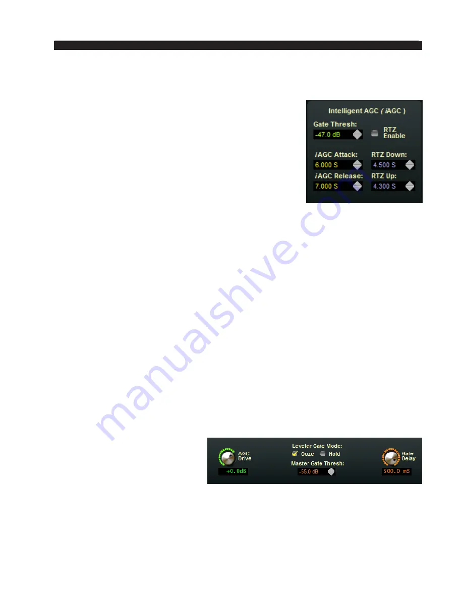
Gate Threshold

The i

AGC 

Gate Thresh control sets the audio level at which 

the iAGC gates (or stops responding to audio). The control can 

be set to OFF to defeat the Gating entirely, or  adjusted over 

the range of ‑79.0dB to ‑20.0dB. There is also an OFF mode 

that defeats the gate when it gets below ‑79.0dB.

i

AGC Attack

Determines how quickly the 

i

AGC will reduce the audio 

level once a change is needed.  The control has a range from 

2.0 seconds to 7.0 seconds.

i

AGC Release  

Determines how quickly the 

i

AGC increases audio once a change is needed. The 

control has the same range as the attack control, 2.0 seconds to 7.0 seconds.

RTZ Enable

When active, allows the i

AGC to return to unity gain in the absence of audio. The 

unity gain value is ‑12dB.

RTZ Down

Sets the time the 

i

AGC takes to return to unity gain when the 

i

AGC is ABOVE unity 

gain (between 0 and ‑12dB of gain reduction) whenever the audio falls below the gate 

threshold. The range is 2.0 ‑ 7.0 seconds.

RTZ Up

Sets the time the 

i

AGC takes to return to unity gain when the 

i

AGC is BELOW unity 

gain (between >‑12dB) whenever the audio falls below the gate threshold. The range is 

2.0 to 7.0 seconds.

Multiband Leveller Controls

AGC Drive

The  AGC Drive control adjusts 

the amount of signal at the input to 

the  i

AGC  and  Leveller/Compressor 

which  then  determines  the  depth  of 

gain  control  achieved.  Driving  the 

 leveller harder (higher drive numbers) 

results in a more consistent on air sound along  with an increased ability to bring up low 

passages in program material when needed. Less drive creates a more “gentle” on air 

sound which then has less capability to bring up low passages. The range of this control  

is ‑12.0dB to +6.0dB.

Summary of Contents for AM-55

Page 1: ...Digital Audio Processor AM 55 600 Industrial Drive New Bern North Carolina 28562 tel 252 638 7000 fax 252 637 1285 Technical Manual...

Page 2: ...Technical Manual Wheatstone Corporation September 2015 Digital Audio Processor AM 55...

Page 3: ...trial Drive New Bern North Carolina 28562 tel 252 638 7000 fax 252 637 1285 Wheatstone Digital Augio Processor Technical Manual 2015 Wheatstone Corporation AM 55 Sep 2015 Ultra High Resolution Process...

Page 4: ...s with deep experience in Digital Signal Processing broadcast audio and other engineering disciplines comprise our design team Led by audio processing expert and broadcast engineering veteran Jeff Kei...

Page 5: ...rs 1 6 Insert Point Future Feature 1 6 AC Power Considerations 1 6 Rear Panel Connections 1 7 Audio Inputs 1 7 Analog In 1 7 AES In 1 8 AM Audio Outputs 1 8 TX Out 1 8 AES Out 1 8 Headphone Monitoring...

Page 6: ...About DHCP and the AM 55 3 6 The AM 55 Network Protocols and Ports Used 3 6 Using the AM 55 GUI 3 7 Dynamic Displays Region 3 8 Frequency Domain Graph 3 8 Managing the Blue Dots Tutorial 3 8 Control...

Page 7: ...rs 3 24 Multiband Limiter Drive 3 24 Limiter Knee 3 25 Bass Clipper Threshold 3 25 Enable 3 25 Bass Style 2 3 25 Filter Shape 3 25 Boost 3 26 Main Clipper Drive 3 26 Pre Emphasis 3 26 AM Diversity Del...

Page 8: ...orking 3 40 Accessing Menu Options 3 41 File Menu Items 3 41 Hardware Menu Items 3 41 AM 55 Hardware Update 3 41 Preset Menu Items 3 43 General Specifications A 3 Interpreting Common Audio Processing...

Page 9: ...udio Connections 1 5 Where to Install the AM 55 1 6 Ratings Encoders 1 6 Insert Point Future Feature 1 6 AC Power Considerations 1 6 Rear Panel Connections 1 7 Audio Inputs 1 7 Analog In 1 7 AES In 1...

Page 10: ...plishedvia100BaseTwired Ethernet Up tofour simultaneous remote control sessions are possible General Purpose Input Output is provided on an RJ 45 to interface to station systems The AM 55 utilizes an...

Page 11: ...nnectors and its chassis has a width of 17 11 32 Space needed in front of rack rails is 3 4 and an additional five inches of space is required for wiring cables to pass through If using only two rack...

Page 12: ...chassis as low as possible this applies to all audio equipment not just the AM 55 particularly when the equipment is located within the electrically hostile environment of a station s transmitter faci...

Page 13: ...to operate correctly when driving the unbalanced load it is recommended that the AM 55 s XLR output Pin 1 ground shield also be connected to Pin 3 Lo noting that this MUST BE DONE at the AM 55 s outpu...

Page 14: ...een that Wheatstone audio processors favorably pass the data watermarking scheme used in the rating service technology regardless of the aggressive ness of the processing being performed Insert Point...

Page 15: ...versa is supported Automatic failover from AES3 or WheatNet IP to analog is instantaneous and based on invalid or missing bits in the AES3 or WheatNet IP stream or after 30 seconds of silence level be...

Page 16: ...Monitoring An overload protected stereo headphone amplifier drives the front panel stereo headphone output located on the left side of the AM 55 s front panel The audio source feeding the headphones...

Page 17: ...g RJ 45 Plug White Orange 5 6 7 8 N C N C 5 6 7 8 Orange White Green Blue White Blue Green White Brown Brown N C N C White Orange Orange White Green Blue White Blue Green White Brown Brown 1 2 3 4 TXD...

Page 18: ...GPI EXTERNAL RESISTANCE 3 3 Volts None 5 0 Volts 330 Ohms 6 0 Volts 470 Ohms 7 5 Volts 820 Ohms 10 0 Volts 1 3 kOhms 12 0 Volts 1 8 kOhms 12 0 Volts 2 4 kOhms 24 0 Volts 3 9 kOhms 30 0 Volts 5 1 kOhm...

Page 19: ...ion whenever switching back and forth between presets in order to compare them When a preset has been recalled and has not been modified the preset s name is displayed in green text within the GUI s c...

Page 20: ...ny factory presets were installed which can vary with software version The total number of presets on the AM 55 s hardware cannot exceed eighty 80 The storage space available for presets on the GUI s...

Page 21: ...PIN 1 LINE RT IN SH PIN 2 LINE RT IN HI PIN 3 LINE RT IN LO XLR F R 2 1 3 page 1 13 AM 55 Input Output Connections AM 55 Sep 2015 TX OUT 1 2 3 XLR M PIN 1 AES OUT SH PIN 2 AES OUT HI PIN 3 AES OUT LO...

Page 22: ...eadphone 2 5 Source Selection 2 5 Headphone Volume 2 5 Presets 2 5 Input 2 5 Input Source 2 5 Input Gain Adjustment 2 6 Pre Emphasis 2 6 Sound 2 6 Texture 2 6 EQ 2 7 Save 2 7 A Note About The Front Pa...

Page 23: ...ver exceed 0dBFS and severe clipping distortion will result if the audio attempts to exceed it Please also note that the LED indicator for the 12dBFS level is yellow in order to warn the operator that...

Page 24: ...ulation levels as they are being generated by the AM 55 s processing OLED Display On the front panel of the AM 55 is an OLED display that allows you to set up configure and place the processor on the...

Page 25: ...or positive modulation Network Shows the current IP Address Subnet and Gateway assigned to the AM 55 These settings can also be edited from this submenu Version Displays the current version of softwar...

Page 26: ...e Volume To adjust the volume level turn the knob to the second option and push the knob You can then adjust the volume to a safe and comfortable level by turning the knob Once complete push the knob...

Page 27: ...low you can correct that here however it is advised to go back and look at where the level discrepancy originated and resolve the issue at that point then return the operating level of the AM 55 to u...

Page 28: ...ant to adjust by highlighting it and pressing in the knob All EQ features are adjustable on a scale from 0 10 with 0 being the lowest setting and 10 being the highest The default for all factory prese...

Page 29: ...t submenu allows you to configure the analog TX1 TX2 and AES output levels The adjustments in this submenu are TX1 Level Tx1 Lvl Sets the level of the processor s balanced TX1 output TX2 Level Tx2 Lvl...

Page 30: ...55 just as it is written in this example The front panel does not allow the user to add leading zeroes but it can be accidently entered into the PC GUI An incorrect way of entering the 192 168 1 155 a...

Page 31: ...rd has been created push and hold the knob to save the password When anyone attempts to access the processor front panel they will be met with a prompt to enter a password To enter a password turn the...

Page 32: ...Domain Graph 3 8 Managing the Blue Dots Tutorial 3 8 Control Area Region 3 10 Input Menu 3 11 Input Source 3 11 Input Signal Presence 3 11 Automatic Input Failover 3 12 Input Level Control 3 12 Input...

Page 33: ...GC Mix 3 23 MB Limiter Menu 3 24 Limiters and Clipper Controls 3 24 Enable Limiters 3 24 Multiband Limiter Drive 3 24 Limiter Knee 3 25 Bass Clipper Threshold 3 25 Enable 3 25 Bass Style 2 3 25 Filter...

Page 34: ...3 35 Side Bar Region 3 36 Preset List 3 36 Preset Library 3 36 Locking Presets 3 36 How to View Preset Changes 3 37 Save Preset 3 37 Config Devices 3 38 Headphone Source 3 38 Headphone Control 3 38 T...

Page 35: ...ment is more than two mouse clicks away TheAM 55 GUI software may control an unlimited number ofAM 55 s via a standard Ethernet network Utilizing TCP and UDP protocols the GUI can be used to control t...

Page 36: ...ist and click on the Select button Now you can place the GUI online by clicking on the button to the left of the Status message The indicator inside the button will be green when theAM 55 GUI is commu...

Page 37: ...tic IP addresses may be open and usable for the AM 55 Sometimes the local network warrants the Subnet and Gateway values to be vastly different but our suggested starting values for the Subnet and for...

Page 38: ...imized on the desktop taken off the screen and or closed by way of the familiar controls at the extreme top right Descriptions of the features and functions of the GUI will follow different discrete r...

Page 39: ...d by manipulating the positions of various Dots on that section s graphical screen Each dot represents one processing band By double clicking a blue dot to highlight it and turn it Red and then draggi...

Page 40: ...ing these steps Now right click again and this time select Flat Drag Grab the line again anywhere left click and drag and move it up and down See how the line pivots at the highlighted point but remai...

Page 41: ...to using the scroll wheel the resolution of the control variation can be increased made finer by holding down the keyboard s Ctrl key while adjusting the control as above OR In most cases you can dou...

Page 42: ...he Input Sources can be selected as either Analog or Digital There is one analog input source the AM 55 s balanced audio inputs on its rear panel There are two types of Digital sources however standar...

Page 43: ...input As you can see to the right the analog controls are shown since the audio source selected in Analog Line In The Analog audio input gain can be adjusted by clicking on the knob and dragging the m...

Page 44: ...edtoremoveinaudibleandunnecessary subsonic energy from the audio signal prior to it being processed By removing this energy processing is cleaner and modulation energy is not wasted by trans mitting s...

Page 45: ...EQ has a frequency range of 2kHz to 20kHz and can have a boost or cut of 14dB The controls of the equalizer may be manipulated in three ways 1 The first is by directly clicking on and dragging the co...

Page 46: ...entry will be made active Manipulating Equalization Curves via Mouse Double clicking on the small crosshair at the top or bottom if it s below the line of the curve turns that section on and off white...

Page 47: ...bout Outboard Processors and Rreevveerrbb Several popular outboard broadband and multiband pre processors on the market have been used in front of all in one processors to achieve one or all of the fo...

Page 48: ...els they must use outboard pre processing ahead of the AM 55 we suggest bypassing the iAGC option in the AM 55 The iAGC was meant to measure the dynamic range in real time of the incoming audio includ...

Page 49: ...dio The unity gain value is 12dB RTZ Down Sets the time the iAGC takes to return to unity gain when the iAGC is ABOVE unity gain between 0 and 12dB of gain reduction whenever the audio falls below the...

Page 50: ...l for when the Leveller enters one of the Gated modes explained above The control can be set to OFF to defeat the Gating entirely or adjusted over the range of 79 0dB to 20 0dB Crossover Frequencies T...

Page 51: ...graphic The lower region of the GUI allows the user to change the threshold and timing of the five band leveller and compressor It also has options for compression ratio and mixer output For more info...

Page 52: ...the blue leveller line when the leveller and compres sor are at the same value of gain reduction When the compressor needs to further reduce gain you will see the blue leveller line appear as the comp...

Page 53: ...veller will increase gain when the audio levels fall as long as they are still above the Gate Threshold setting discussed previously The adjustment range of the control is from 1 0 seconds to 7 0 seco...

Page 54: ...1 The Ratio for each band may be set individually and the Ratio settings apply to both the Leveller and Compressor simultaneously AGC Mix The Mix control may be used to tailor the spectral mix of the...

Page 55: ...and sounds best when it just protects the clipper from overshoot from the dynamics stage That s what it is there for Our limiters have no gating and should only be driven so that a few dB of limiting...

Page 56: ...t more freely without causing IM distortion in the main clipper When the bass clipper is off bass is treated exclusively in the main clipper only Bass Style 2 By default the bass enhancer is set to St...

Page 57: ...whatisrequiredforyourregion and transmission system The options are Flat pre50uS and NRSC AM Diversity Delay TheAM 55 is equipped with an internal digital delay to compensate for the corresponding del...

Page 58: ...l value of the option being adjusted For instance when Release is being adjusted the left scale shows the release times in mS Attack This control determines how quickly the limiter bands respond to au...

Page 59: ...o properly set low frequency tilt correction in older plate modulated transmitters Positive Peak Threshold This control governs the amount of positive peaks allowed by the AM 55 s clipper as compared...

Page 60: ...te is displayed below the dropdown menu In the example above the input is at 44 1kHz and the user has selected a change to 48kHz on the output TX Outputs Many AM transmitters require an output drive o...

Page 61: ...t complimentary to what the transmitter will do to the waveform later In essence LF Tilt EQ is a specialized extremely low frequency equalizer that tilts the waveform in the direction OPPOSITE to how...

Page 62: ...f final clipping or bass equalization Doing so can cause stress on internal components and lead to failure or worse HF Correction The performance of all AM transmission systems is constrained to varyi...

Page 63: ...re that at this point the HF Corr EQ L level controls are set for 0dB 4 Turn on the AM 55 Tilt Test by clicking the check box 5 Using an oscilloscope connected to a low level RF sample of the transmit...

Page 64: ...atic between presets and only the sound adjustments are changed Send Metering Data Over TCP IP By default the AM 55 utilizes the UDP protocol for transmitting metering data to the remote GUI the TCP p...

Page 65: ...s no default password in the AM 55 If you are setting this up for the first time you can skip the Password part and just enter the New Password and Verify the new password Other options in this menu i...

Page 66: ...means Please contact the factory for the procedure if it become necessary GUI Access The system allows you to grant access at certain levels of permission in order to control the privileges of those a...

Page 67: ...talk stations that need maximum coverage Preset Library When the Library button is pressed a window styledialogboxappears containing threepanels Thelargepanelontheleftshows the presets currently stor...

Page 68: ...opened highlight anypresetyou dliketocomparewiththecurrent preset running on the processor Then right click andselectViewandDifffromthesub menu You will see the window on the right open Any parameter...

Page 69: ...hain as follows Input Output of the audio input selector analog or AES Ana Inp Audio appearing on the analog line input Dig Inp Audio appearing on the digital input whether it be WheatNet IP or AES3 A...

Page 70: ...which the GUI is connected or with which it is attempting to connect shows in the Device window in amber text Double clicking on the name area bringsuptheDevicesdialogbox Alist ofAM 55 devices that t...

Page 71: ...mode Offline however is more of a management utility intended for creating presets or tweaking them without needing to listen to them on the host AM 55 Changes can be made to presets and configuratio...

Page 72: ...licking anywhere on the main AM 55 Control Panel Please note that most of the Hardware related items require you to be connected Online to the AM 55 because that is where the data must come from Sub m...

Page 73: ...e audio from the air without it being an issue To update theAM 55 right click on any portion of the control area in any screen of the remote GUI to open pop up menu tree Select the HardwareandthenUpda...

Page 74: ...estions about an update feel free to contactWheatstone Technical Support at techsupport wheatstone com Presets Menu Items The Presets menu tree may be accessed by right clicking anywhere on the main A...

Page 75: ...ms A 8 Background A 8 Audio Terms and Wheatstone Processing A 9 Thump Rumble Bottom A 9 Punch Boom Tubby Warm A 10 Mud A 10 Honk A 10 Whack A 10 Fuzzy Tinny A 11 Sibilance A 11 Treble Bright Open A 11...

Page 76: ...page A 2 AM 55 Sep 2015 A P P E N D I C E S Appendix A General Specifications A 3 Contents...

Page 77: ...t Gain Adjustment Ranges Gain Range 12dB Gain Adjustment Resolution 0 5dB Gain Calibration A gain control setting of 0 0 aligns an external 0dBFS signal with the AM 55 s 0dBFS internal reference Input...

Page 78: ...6 0dB in 0 5dB steps AGC Compressor Thresholds 50dBFS to 80dBFS AGC Density 0dB to 6dB Leveller Attack 100mS to 1000mS Leveller Release 1000mS to 7000mS Compressor Attack 10mS to 50mS Compressor Relea...

Page 79: ...est Clips test oscillator waveform at 50 amplitude Bandwidth 4 5kHz 5kHz 6kHz 7 5kHz 10kHz Full 20kHz LF Tilt Correct Frequency 5Hz to 100Hz LF Tilt Correct Q 0 25 to 3 00 LF Tilt Correct Level 0 0 6...

Page 80: ...resetsallowingthepreservationofthecompleteprocessing environment Optionally Input and Output settings may be stored and recalled with presets Preset Encryption Presets are encrypted using the AM 55 in...

Page 81: ...rpreting Common Audio Processing Terms A 8 Background A 8 Audio Terms and Wheatstone Processing A 9 Thump Rumble Bottom A 9 Punch Boom Tubby Warm A 10 Mud A 10 Honk A 10 Whack A 10 Fuzzy Tinny A 11 Si...

Page 82: ...uddy is not usu ally used in a positive sense while warm on the other hand often means the sound has a pleasing low end See the confusion here The terms themselves the ones that we use to describe sou...

Page 83: ...s enhancement features The AM 55 is equipped with a very specialized bass clipper system This system is an intelligent clipper that samples the bass frequency relationship between bands 1 and 2 and is...

Page 84: ...sor band to add too much gain In most cases it s a good idea to keep from boosting energy in this region In fact additional clarity and detail can be created by a broad equalization cut in the range b...

Page 85: ...excessive sibilance is an issue and there is no microphone processor to control it lowering the AM 55 s Band 4 to Band 5 crossover setting and or using a slightly faster attack time on the Band 5 Leve...

Page 86: ...y towards achieving an open and easy to listen to sound When this is the target sound starting with one of our Classical or Jazz presets and then turning things up is a good way to approach achieving...

Page 87: ...page A 13 AM 55 Sep 2015 A P P E N D I C E S Contents Appendix C WheatNet IP Configuration A 14 Adding AM 55 to The WheatNet IP System A 14...

Page 88: ...n and you are logged into the system we must create a new device for AM 55 Because AM 55 is not a BLADE it appears and operates as a peripheral device within the WheatNet IP system Our Sideboard an ou...

Page 89: ...ged the default names begin with AM55 and will be AM55 Input and AM55 Out Of course these signals may be manually crosspointed and locked if desired to make connections or it may be done through the m...

Reviews: