Wire
Starts at:
Ends at:
Use, Remarks
No.
(Subunit, PC board, terminal)
(Subunit, PC board, terminal)
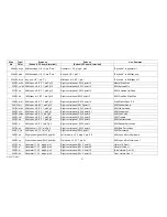
417 W, w/r
Le ftcontrol panel, SW 3, point 23 l
L/M sound comp., SC 3, plug 1, pin 9 I
L/M Cancel
418 W, ye/bl Left control panel, SW 3, point 18
M/M sound comp., SC 5, plug 1, pin 9
M/M Cancel
419 W w/bn Leftcontrolpanel,SW 3,point12
U/M sound comp., SC 5, plug 1, pin -9 1
U/M Cancel
420 W, w/bn Left control panel, SW 3, point 28
L/M sound comp., SC 3, plug 2, pin 15
L/M Address A 3
421 W, w/bn Left control panel, SW 3, point 25
L/M sound comp., SC 3, plug 2, pin 16
L/M Address A 2
422 W, w/bn Left control panel, SW 3, point 26
L/M sound comp., SC 3, plug 2, pin 17
L/M Address A 1
423 W, w/bn Left control panel, SVV3,point 27
L/M sound camp., SC 3, plug 2, pin 18
L/M Address A O
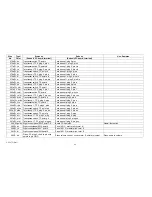
424 W,ye/bk Left control panel, SW 3,point9
M/M sound comp., SC 5, plug 2, pin 14
M/M Address A 4
425 W,ye/bk Left control paneI,SW 3,point22
M/M sound camp., SC5,plug 2, pin 15
M/M Address A 3
426 W, ye/bk Left control panel, SW 3, point 19
M/M sound comp., SC 5, plug 2, pin 16
M/M Address A 2
427 W,ye/bk Left control panel, SW 3, point 20
M/M sound comp., SC 5, plug 2, pin 17
M/M Address A 1
428 W, ye/bk Left control paneI,SW 3,point21
M/M sound camp., SC 5, plug 2, pin 18
M/M Address A0
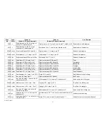
429 W,w/bk
Left control panel, SW 3,point10
U/M sound comp., SC 5, plug Z, pin 14
U/M Address A4
430 W,w/bk
Left control paneI,SW 3,point16
U/M sound comp., SC 5, plug 2, pin 15
U/M Address A 3
431 W, w/bk Left control panel, SW 3, point 13
UIM sound comp., SC 5, plug 2, pin 16
U/M Address A 2
432 W,w/bk
Left control paneI,SW 3,pointl4
U/M sound comp., SC 5,plug2,pin 17
U/M Address A1
433 W, w/bk Left control panel, SW 3, point 15
fU/M sound comp., SC 5, plug 2, pin 18
U/M Address A0
434 W, w
Program doubling switch
L/M sound camp., SC.3, plug 2, pin 13
435 W, w
Program doubling switch
M/M sound comp., SC5,plug 2, pin 13
436 W,w
Program doubling switch
U/Msound comp., SC5,plug 2, pin 13
437 W, w
Program doubling switch
Left control panel, SW 3,.point 6
Type/
Color
1999 Thomas Erlebniswelt Musik
This document has been reproduced for the benefit of current owners of WERSI organs. It should not be used for any commercial purposes.
AM 075 (Part)
56
Summary of Contents for GALAXY
Page 1: ...Master Assembly GALAXY AM 075 AM 075 Part 1 ...
Page 4: ...Figure 1 Layout of the building blocks in the organ top AM 075 Part 4 ...
Page 5: ...Figure 2 Block diagram of the audio distribution and associated DC controls AM 075 Part 5 ...
Page 6: ...AM 075 Part 6 ...
Page 33: ...Figure 4 Schematic layout of the wiring harness GO 4 AM 075 Part 33 ...


