AM 075 (Part)
30
key of the middle manual. If necessary, touch up the
"Orchestra Intonation" for "zero beat".
7. Set the transposer switch to any desired position. Consult
the Tuning Table and adjust the trim pot that corresponds to
the particular transposer position on TP 2 // to achieve "zero
beat". There is no need to change keys.
8. Set the trim pots P 12 thru P 22 on TP 211 to tune that
transposer for the tone generator II.
As a result, both organ generators should be transposable in
half-tone steps and they should stay in tune at every
transposed key.
Note
: You will find that it requires a very fine touch when adjusting
the trim pots in order to achieve a true "zero beat" in all cases.
9. Adjust the trim pots P1 thru P11 on TP 21 until "zero beat" is
reached between the accompaniment generator and the
middle manual generator. Depress and hold the middle A
key of the middle manual.
Depress the A key of the second octave on the lower manual.
This will hold the A note of the auto accompaniment if the
"Memory" is on. Consult the Tuning Table for the trimpot
assignment vs. transposer position. Also refer to the manual AM
481 or AM 841 for information on tuning.
3.29 Testing of the Arpeggio/Glissando
Refer to the assembly manual AM 425 "Arpeggio/ Glissando" for
information on the installation, wiring and testing.
3.30 Testing of the Studio Amplifiers
If you have elected to install the optional studio amplifiers (balanced
600 Ohms audio outputs used in recording studios) install the two
boards S V 7 and mate the connectors as shown in Fig. 7 9. The
assembly manual AM 545 contains information on testing and
adjustments of the studio amplifiers.
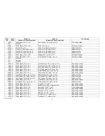
Table 1Tuning Table for the Twin Transposers
Transposer
Position
Frequency at
test point -
3520 Hz" in
Hz
Trimpot on
TP21 (Gen l)
M/Man
Trim pot on
TP 211(Gen
II) U /Man
Trimpot on TP
21 (Accomp.)
Accompanime
nt
Key to hold
to achieve
'°middle A"
F #
2489
P17
P17
P 6
D #
G
2637
P18
P18
P7
D
G #
2794
P19
P19
P 8
C #
A
2960
P 20
P20
P 9
C
A #
3136
P 21
P 21
P10
B
B
3322
P22
P22
P11
A #
Summary of Contents for GALAXY
Page 1: ...Master Assembly GALAXY AM 075 AM 075 Part 1 ...
Page 4: ...Figure 1 Layout of the building blocks in the organ top AM 075 Part 4 ...
Page 5: ...Figure 2 Block diagram of the audio distribution and associated DC controls AM 075 Part 5 ...
Page 6: ...AM 075 Part 6 ...
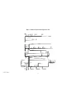
Page 33: ...Figure 4 Schematic layout of the wiring harness GO 4 AM 075 Part 33 ...


