operative, the problem is to be found on the circuit board where the
electronics is located.
3.2 Preparation of the Organ
It is necessary that we have a defined initial setup of the organ
before we start to activate the various subunits. Set the switches
and controls as follows:
( ) All tongue tab switches off (up). ( )All rocker switches off
(pushed in on top).
( ) All drawbars, including the master controls, pushed home.
( ) All push button switches on both slanted control panels off (in
the "out" position).
( ) Transposer switch in position C (standard pitch).
( ) "Slalom" control (left control panel) at its right hand stop.
( ) Push the AC on/off switch down.
( ) Set all trim pots o n both preamplifiers VV 1 to the centre of
rotation.
( ) Connect the speakers to the organ.
3.3 First-Time Power On
This is the moment of truth. We hope that you appreciate the
significance of the impending action. Optimists, at this moment,
unplug the soldering iron and put it back in the closet. Pessimists,
on the other hand, fight a certain tightness in the stomach area.
Plug the AC line cord into a grounded outlet. If nothing happens
you should mark it as a success. Pushing the button at the lower
right corner of the right control panel (you performed this step in the
preceding paragraph II) turned the organ off.
Now push the AC o n/off button again to release it which turns the
organ on. Limit this first on-period to about 3 seconds and turn it off
again.
If your eyes, nose and other senses did not receive any "smoke
signals" or strange noises from within the organ or from the
speakers turn the organ on again. You should be able to notice the
following:
( ) The AC on/off button should be lit.
( ) The tongue tab illumination should be lit. ( )The pedal spot lights
should be on.
( ) The 8 push button "Instruments Delete" on the left control panel
should be lit.
( ) The speakers should produce a faint noise, coming from the
operating power amplifiers.
3.4 Preliminary Tests
1. Check the presence of the power supply voltages by using a
voltmeter. Measured against ground you should be able to
AM 075 (Part)
9
Summary of Contents for GALAXY
Page 1: ...Master Assembly GALAXY AM 075 AM 075 Part 1 ...
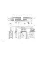
Page 4: ...Figure 1 Layout of the building blocks in the organ top AM 075 Part 4 ...
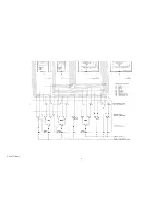
Page 5: ...Figure 2 Block diagram of the audio distribution and associated DC controls AM 075 Part 5 ...
Page 6: ...AM 075 Part 6 ...
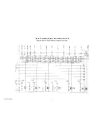
Page 33: ...Figure 4 Schematic layout of the wiring harness GO 4 AM 075 Part 33 ...


