Wire
Type/
Starts at:
Ends at:
Use, Remarks
No.
Color
(Subunit, PC board, terminal)
(Subunit, PC board, terminal)
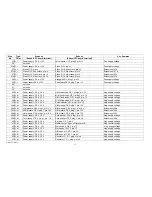
48 W, bl
Power supply, PS 4, -15 V
Piano, P11, plug 3, pin -15
Neg. supply voltage
49 W, bl
Power supply, PS 4, -15 V
L/M keyers, V 3, pin -15
Neg. supply voltage
50 W, bl
Power supply, PS 4, -15 V
M /M keyers, V 3, pin -15
Neg. supply voltage
51 W, bl
Power supply, PS 4, -15 V
U/M keyers, V 3, pin -15
Neg. supply voltage
52 W, bl
Power supply, PS 4, -15 V
Left control panel, SW 4, point -15 V
Neg. supply voltage
53 W, bl
Power supply, PS 4, -15 V
Left control panel, "Wah wah"term. A
N eg. control voltage
54a W, bl
Power supply, PS 4, -15 V
Right pream p, VV 2, plug 5, pin -15
Neg. supply voltage
54b W, bl
Right preamp, VV 2, plug 5, pin -15
Left preamp, V V 2, plug 5, pin -15
Extension of 54a
55 W, bl
Power supply, PS 4, -15 V
Left control panel, SW 3, point - 15 V
Neg. supply voltage
56 W, bl
Power supply, P S 4, -15 V
Piano, PI 13, pin -V
N e, supply voltage
57a W, bl
Power supply, PS 4, -15 V
U/M envelope, H K 13, pin -15
Neg. supply voltage
57b W, bl
U/M envelope, H K 13, pin -15
U/M bus bar
Keying voltage
58 W, bl
Power supply, PS 4, - 15 V
Couplers, K 1, pin -15
Neg. supply voltage
59a W, bl
Power supply, PS 4, -15 V
M/M envelope, H K 13, pin -15
Neg. supply voltage
59b W, bl
M/M envelope, H K 13, pin -15
M/M bus bar
Keying voltage
60a W, bl
Power supply, PS 4, -15 V
L/M envelope, H K 13, pin -15
Neg. supply voltage
60b W,bl
L/M envelope, H K 13, pin -15
L/M bus bar
Keying voltage
61 W,bl
Power supply, PS 4, -15 V
Arpeggio AG 1, plug 3, pin 20
Neg. supply voltage
62 W, bl
Power supply, PS 4, -15 V
Pedal electr., P E 36, plug 7, pin -15
N eg. supply voltage
63 W, bl
Power supply, PS 4, -15 V
Right control panel, "Sp.eff.rate", term. S
Neg. control voltage
64 W,bl
Power supply,PS4,-15V
RightcontrolpaneI,SW 6, point-15
Neg. supply voltage
65 W, bl
Power supply, PS 4, - 15 V
Right controlpaneI,SW 5, point -15
Neg. supply voltage
66a W, bl
Power supply, PS 4, -15 V
"Read-in" switch
Neg. control voltage
66b W, bl
"Read-in" switch
L/M sound comp., SC 3, plug 2, pin 24
Neg. supply voltage
67a W, bl
"Read-in" switch
M/M sound comp., SC 5, plug 2, pin 24
Neg. supply voltage
67 b W, bl
"Read-in" switch
U/M soun d comp., SC 5, plug 2, pin 24
N eg. supply voltage
68 W, bl
"Read-in" switch
"Memory doubling" switch
Neg. control voltage
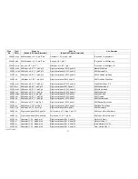
69 VV, bk
Power suppiy,PS4,G N D
L/M fixed stops, GP1,plug2,pin G N D
G N D = Ground
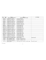
70 VV, bk
Power supply, PS 4, G N D
M/M fixed stops, G P 1,plug 2, pin G N D
G N D
71 W, bk
Power supply, PS 4, G N D
U/M I fixed stops, G P 1, plug 2, pin G N D
G N D
72 W, bk
Power supply, PS" G N D
U/M If Axed stops, DS 1,plug 1,pin 7
G N D
AM 075 (Part)
36
Summary of Contents for GALAXY
Page 1: ...Master Assembly GALAXY AM 075 AM 075 Part 1 ...
Page 4: ...Figure 1 Layout of the building blocks in the organ top AM 075 Part 4 ...
Page 5: ...Figure 2 Block diagram of the audio distribution and associated DC controls AM 075 Part 5 ...
Page 6: ...AM 075 Part 6 ...
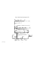
Page 33: ...Figure 4 Schematic layout of the wiring harness GO 4 AM 075 Part 33 ...


