Wire
Starts at:
Ends at:
Use, Remarks
No.
(Subunit, PC board, terminal)
(Subunit, PC board, terminal)
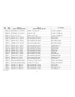
350 S, r
Pedal electronics, P E 36, plug 6, co
nd.to pin 17,shield to pin 16
Right pream p, V V 2, plug 3, cond.to pin E 7,shield cut off Pedal audio to both preamps
351 S, r
Pedal electronics, P E 36, plug 6,
cond.to pin 17,shield to pin 16
Wersivoice I, W V 7, cond.to pin 6, shield cut off
Pedal audio to Wersivoice I
352a W, w/bk Right control paneI,SW 6, point 40 v
Right preamp, V V 2, plug 4, pin S7
Pedals to right preamp
352b W, w/bk Right pream p, V V 2, plug 4, pin S 7
'Left preamp, V V 2, plug 4, pin S 7
Pedals to left preamp
353 W,bn
Right control panel, SW 6, point 40 w
Wersivoice I, W V 7, pin 6 c
Pedals to Wersivoice I
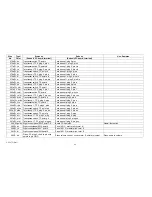
354 W,bn
Pedal electr.,P E 36, plug 5, pin 7
Right control panel, SW6,point37
Tuba
355 W,ye
Pedal electr.,PE 36, plug 5, pin 6
Right control paneI,SW 6,point39
Contrabass
356 W,gy
Pedal electr., P E 36, plug 5, pin 5
Right control panel, SW 6, point 36
Bass guitar
357 W, w
Pedal electr.,P E 36, plug 5, pin 4
Right control paneI,SW 6, point 38
Trumpet
358 W,pk
Pedal electr.,P E 36, plug 5, pin 3
Right control paneI,SW 6,point34
Long Sustain
359 W,r/bl
Pedal electr., P E 36, plug 5, pin 2
Right control panel, SW 6, point 33
Short Sustain
360 W,ye/bn Pedal electr.,P E 36, plug 5, pin 1
Right control paneI,SW 6, point 35
Pedal Drawbars
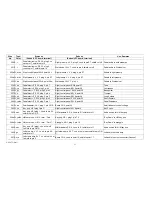
361 W, bn
Sweilindicator, LA 1, plug 1, pin L D R Board CO 4, point 32
Swell indicator control voltage
362 W,ye
Key pop, H P1,plug1,pin C
Right control paneI,SW 6,point8
Key Pop on
363 So bk
Key pop, HP 1,plug 1, con d.to pin 02,
shield to pin G N D
L/M drawbars, Z R 4, co nd.to R 1,shield cut off
Audio source for L/M key pop
364a W,ye/bn LIM envelope, H K 13, term. "Perc."
Key pop, HP 1,plug 1, pin T 2
"Key Down" to L/M key pop
364b W,ye/bn L/M envelope, H K 13, term. " Perc„"
Arpeggio, AG 1, plug 2, pin 14
"Key Down" to arpeggio
365 So bn
Key pop, HP 1,plug1, con d.to pin 0
1,shield to pin G N D
M/M drawbars,Z R 4, con d.to R 1,shield cut off
Audio source for M/M key pop
366 S,gn
Left prea mp, V V 1, co n d.to pin A3,
shield cut off
Left studio amp, SV 7, co n d.to pin Input, shield to pin G N
D
Left audio to studio amp
367 So ye
Left studio amp, SV 7, co nd.to pin 0 ut
1,shield to pin 0
Board CO 4, con d.to point 18,shield to point 17
Left audio to output connector (Cannon)
Type/
Color
AM 075 (Part)
53
Summary of Contents for GALAXY
Page 1: ...Master Assembly GALAXY AM 075 AM 075 Part 1 ...
Page 4: ...Figure 1 Layout of the building blocks in the organ top AM 075 Part 4 ...
Page 5: ...Figure 2 Block diagram of the audio distribution and associated DC controls AM 075 Part 5 ...
Page 6: ...AM 075 Part 6 ...
Page 33: ...Figure 4 Schematic layout of the wiring harness GO 4 AM 075 Part 33 ...


