background image

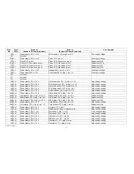
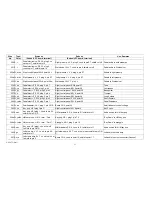
Wire  

Type/ 

Starts at: 

Ends at: 

Use, Remarks 

No. 

Color 

(Subunit, PC board, terminal) 

(Subunit, PC board, terminal) 


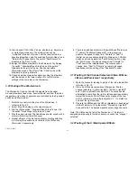
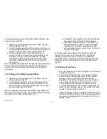
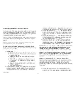
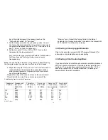
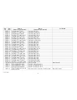
104 W,bk 

Power supply,PS 4,G N D 

Piano PI 13,term.G N D 

G N D 

105 W,bk 

Power suppIy,PS4,G N D 

U/M envelope, H K 13, term. GN D 

G N D 

106 W,bk 

PowersuppIy,PS4,G N D 

Couplers, K 1, term. G N D 

G N D 

107 W,bk 

Power supply,PS4,G N D 

M/M envelope, H K 13, term. G N D 

G N D 

108 W,bk 

Power supply,PS4,G N D 

L/M envelope, HK 13,term.G N D 

G N D 

109 W, bk 

Powersupply, PS 4, G N D 

Arpeggio, AG 1, plug 3, pin 19 

G N D 

110 W, bk 

Power supply, PS 4, G N D 

Pedal Own, P E 36, plug 7, pin GN D 

G N D 

111 W,bk 

Power suppIy,PS 4, G N D 

Right control panel, SW 6, point G N D 

G N D 

112 W,bk 

Power supply, PS 4, G N D 

Right control panel, SW 5, point G N D 

G N D 

113 W,bk 

Power supply,PS4,G N D 

M/M sound comp., SC 5,plug2,pin23 

G ND 

114 W,bk 

Power supply,PS4,G N D 

U/M sound comp., SC 5, plug 2, pin 23 

G N D 

115   

not used 


116   

not used 


117a W, w/bl 

Power supply, PS 4,+25 V D C 

Lower lamp at WE R Sllogo 

Unregulated D C 

117b W,w/bl 

Lower lamp at WE RSllogo 

Upper lamp at WERSllogo 

Extension of 117a 

117c W,w/bl 

Upper lamp at WERSllogo 

Stop tablet illumination 

Extension of 117b 

118 W,gn/bn  L/M sound comp., SC 3, plug 1, pin 1 

L/M fixed stops, G P 1, plug 2, pin PM 

PMU = L/Man program control voltage 

119 W,gn/bn  L/M sound comp., SC 3, plug 1, pin 2 

Switchbank "DrawbarPresets"switch " L/M Preset 1'; US 1, 
point p M 

PM U 

120 W,gn/bn  L/M sound comp., SC 3, plug 1, pin 3 

Right control paneI,SW 6, point PM U 

P M U 

121 W,gn/w  M/M sound comp., SC 5, plug 1, pin 1  M/M fixed stops, GP1,plug2,pin PM 

PM M = M/Man program control voltage 

122a W,gn/w  M/M sound comp., SC 5, plug 1, pin 2 

Switch bank " Drawbar Presets'; switch " M /M Preset 1'; 
US 1, point pM 

PM M 

122b W,gn/w 

Switchbank " Drawbar Presets'; switch 
"M/M Preset 1", US 1, point p M  

Switchbank "Wersivoice I" (4 pos.), US 1, point pM 

Extension of 122a 

122c W,gn/w  Switchbank "Wersivoice1" (4 pos.) 

Channel selectors, S 4 K, point 22 

Extension of 122b 

AM 075 (Part) 

38 

Summary of Contents for GALAXY

Page 1: ...Master Assembly GALAXY AM 075 AM 075 Part 1 ...

Page 2: ... Stops 14 3 10 Testing of the M Man Fixed Stops 16 3 11 Testing of the U Man II Fixed Stops 17 3 12 Testing of the U Man I Fixed Stops 19 3 13 Testing of the Tongue Tab Switches Drawbars or Fixed Stops 19 3 14 Testing of the Drawbar Fixed Stops switches of the M Man and U Man respectively 19 3 15 Tuning of the Tone Generators and Testing of the Generator Functions 20 3 16 Testing of the Functions ...

Page 3: ...3 30 Testing of the Studio Amplifiers 30 3 31 Testing of the Sound Computer 31 4 Final Steps 31 2 1 FIGURES Figure 1 Layout of the building blocks in the organ top 4 Figure 2 Block diagram of the audio distribution and associated DC controls 5 Figure 3 Schematic diagram of the drawbar presets PZ4 7 Figure 4 Schematic layout of the wiring harness GO 4 33 2 2 TABLES Table 1Tuning Table for the Twin ...

Page 4: ...Figure 1 Layout of the building blocks in the organ top AM 075 Part 4 ...

Page 5: ...Figure 2 Block diagram of the audio distribution and associated DC controls AM 075 Part 5 ...

Page 6: ...AM 075 Part 6 ...

Page 7: ...Figure 3 Schematic diagram of the drawbar presets PZ4 Applies also to PZ6 with different component numbers AM 075 Part 7 ...

Page 8: ...to call this wire simply Test lead in the future Never allow the alligator clip to touch ground all black wires and metal chassis parts respectively nor 1 5 V all red wires As you may have noticed by now all functions of the organ are controlled by a negative control voltage This control voltage may stem from a front panel switch from the sound computer or from our test lead The conversion of this...

Page 9: ...t back in the closet Pessimists on the other hand fight a certain tightness in the stomach area Plug the AC line cord into a grounded outlet If nothing happens you should mark it as a success Pushing the button at the lower right corner of the right control panel you performed this step in the preceding paragraph II turned the organ off Now push the AC o n off button again to release it which turn...

Page 10: ...oving the insulation at both ends over a length of about 1 4 Attach a 1 long piece of heavy bare hookup wire to one end of this wire Stick the end with the bare wire into the rear opening of the connector on the left preamplifier namely into the hole with leads to pin A 2 on plug 5 This location corresponds to the audio output of the left preamplifier audio input of the left power amplifier Turn o...

Page 11: ... connector attached to branch 7 3 of the harness G O 4 with the pins of plug 1 on the board P Z 4 L Man referring to Fig 84 4 Turn on the organ Depress a key near the centre of the lower manual and hold it depressed Wedge some non metallic material between the key and the manual spacer N o tone should be heard yet 5 Clip the test lead 15 V to pin S 5 plug 4 of the right preamplifier S 5 is the con...

Page 12: ...t to right across the individual drawbars If you listen closely you will hear two tones when either of the right most two drawbars is pulled The eleventh drawbar controls the sum of two footages namely the Seventh 1 1 7 and the Ninth 8 9 while the twelfth drawbar is fed with the two footages Third 4 5 and Fifth 2 3 Release the key of the lower manual 10 Check all footages over the entire lower man...

Page 13: ...e trouble is limited to the envelope control boards The latter is unlikely since these boards were tested earlier 3 7 Testing of the Middle and Upper Manuals respectively Repeat all tests of the preceding chapter VI with the following changes The middle manual drawbar signals are applied to the inputs E 3 of the preamplifiers and the corresponding control inputs are the terminals S 3 Similarly the...

Page 14: ...he organ off 3 9 Testing of the L Man Fixed Stops 1 Depress and hold a key of the lower manual 2 Activate a few fixed stops of the lower manual by flipping the corresponding tongue tabs down 3 Pull the master control L M an Volume grey drawbar out halfway 4 Mate the connector attached to branch 9 6 of the harness GO 4 with the pins of plug 2 on the board G P 1 L Man referring to Fig 89 5 Clip the ...

Page 15: ... consult wire list If you get sound the problem is located on the voicing motherboard G P 1 Remove it from the lid and inspect the narrow foil pattern very carefully 8 Check the sounds of each fixed stop with the description below while playing the lower manual Note 1 Minor variations may be noticed since the tone generator is not set to its correct pitch Note 2 Do not jump to conclusions if a par...

Page 16: ...ixture less brilliant than the Cymbal V but fuller towards the bass end 3 10Testing of the M Man Fixed Stops Test the middle manual fixed stops in a similar fashion This time however clip the test lead 1 5 V to pin S 4 of either preamplifier Mate the connector attached to branch 9 5 with plug 2 of the M Man fixed stops board G P 1 referring to Fig 89 Note that the audio output from the middle manu...

Page 17: ...softer towards the treble end Repeats at the C key of the 4 octave and above The 3 highest C keys produce the same note 14 Mixture II Piercing add on brightness over the entire manual not a solo stop 3 11Testing of the U Man II Fixed Stops The U Man II fixed stops are located on the voicing block of the upper manual which is not equipped with stop switches We already connected the board DS1 there ...

Page 18: ...ow at the bass end 2 Saxophone 16 Rich in harmonics with traces of a stopped pipe at middle to low pitches very reed like 3 Accordion 16 Very brilliant with lots of harmonics contains the aliquotes 1 3 5 and 1 1 3 respectively 4 Trombone 16 Bold and brassy 5 Cello 16 Plenty of harmonics but with a warm character 6 Clarinet 8 Pitched one octave above the 16 stops typical hollow woodwind sound 7 Hor...

Page 19: ...sition 3 Activate a few stops 4 Pull a few L Man drawbars about halfway must include the volume drawbar left most black drawbar of the group 5 Mate the connector leading to plug 4 of the right preamplifier referring to Fig 7 0 6 Play on the lower manual The fixed stops should sound from the right speaker provided the channel selector switch still is in its up position Flipping the switch Drawbars ...

Page 20: ...h octave on the middle manual This tone should be middle A having a frequency of 440 Hz There are many methods by which this can be achieved frequency counter tuning fork tuning flute or another instrument of known tuning Adjust the cermet trim pot P 2 on the tone generator I until the middle A has the exact pitch If you are using another instrument as a reference listen for the beat frequency whi...

Page 21: ...n Slow Vibrato The formerly fast vibrato approximately 6 Hz should 31 slow to about 4 Hz Note The switches Vibrato II Vibrato III and Slow Vibrato are effective only if either Delayed Vibrato and or Coot Vibrato is turned on 24 Next we are going to test the autoglide modes of the generator 11 Release all push buttons in the 3rd row from the top o n the right control panel 25 Set the transposer swi...

Page 22: ... The left channel is not operating yet 5 Play on both the U Man and M Man respectively The clarinet should sound on the U Man and the trombone on the M Man Adjust the volume controls grey drawbars to suit 6 Depress the push button Program Coupler on the left control panel top right hand corner It should light up and also should cause the button Manual Coupler on the right control panel to light up...

Page 23: ...th fixed stops borrowed from two different manuals Any desired degree of ensemble tuning can be selected by the corresponding 4 push buttons Try it out by selecting some brass stops on both manuals and use the ensemble tuning button III c Manual Coupler and Orchestra Coupler on Select any fixed stops on the upper manual Set the Drawbar Fixed Stops switch of the M Man to fixed stops down Two sets o...

Page 24: ...e of rotation Select a heavy registration almost all fixed stops active on the M Man 5 While holding a full chord o n the middle manual turn the trim pot P 2 Input on the Wersivoice I clockwise until you detect some distortion Turn the trim pot P 2 counter clockwise for about 15 degrees such that the distortion disappears 6 Flip the M Man switch Fixed Stops to Wersivoice back and forth You probabl...

Page 25: ...he preceding chapter starting with step 4 but using the switches and controls of the U Man and Wersivoice Il respectively 6 There is an additional switch in the switchbank Wersivoice II namely Fast Slow Speed shift In its normal up position the speed change from Chorale to Fast is inertial as you experienced with the Wersivoice I Flip this switch down and operate the Fast Chorale switch using the ...

Page 26: ...tches which are missing with respect to the U Man special effects are a Drawbars Only preset 2nd and 3rd harmonics can be selected but not manually settable drawbars b Fast Rate Medium Rate and Short Rate The special effects rate is slow as tong as the button Variable Rate is released Depressing the latter button activates the rotary control Spec Eff Rate on the right control panel The special eff...

Page 27: ...tons Tuba Trumpet and Contrabass respectively These fixed stops of the pedals should be volume adjustable by the black draw bar Fixed Stops The Tuba is a 16 stop while the Trumpet and Contrabass belong to the 8 rank The sustain controls d o not influence the fixed stops 11 Depress the button Bass guitar and release all other buttons of the pedal group bottom row Play the pedals and you should be a...

Page 28: ...e the connectors of branch 8 1 with the pins on the swell indicator board L A 1 referring to Fig 85 Depending on the swell pedal position a few LED lights should be lit 2 Set the swell pedal to the low volume stop None of the LED or maybe the bottom one should light up 3 Set the swell pedal to its high volume stop If necessary adjust the trim pot on the board LA 1 such that all LED s are just lit ...

Page 29: ...ute ear etc adjust the master pitch control on AP 1 G to set it correctly 3 Set the transposes switch to C Depress and hold the key G Set the trim pot P 12 on the twin transposer l next to Key Pop until the tone is pitched to middle A 440 Hz again 4 Set the transposes switch to D Depress and hold the key G Set the trim pot P 13 on the same twin transposes until the tone returns to middle A 440 Hz ...

Page 30: ...the second octave on the lower manual This will hold the A note of the auto accompaniment if the Memory is on Consult the Tuning Table for the trimpot assignment vs transposer position Also refer to the manual AM 481 or AM 841 for information on tuning 3 29Testing of the Arpeggio Glissando Refer to the assembly manual AM 425 Arpeggio Glissando for information on the installation wiring and testing...

Page 31: ...tstanding musical instrument which will provide you with a lot of excitement and enjoyment for a long time to come We are convinced that this will be ample compensation for your work and possibly some frustrating stumbling blocks luring the assembly period Now once more clean out the instrument by removing any residual debris temporary wires hardware tools etc Keep an eye open to detect the smalle...

Page 32: ... for your inauguration concerts marked by the absence of demonstration effects You are embarking on the second phase of a long journey namely the never ending discovery of new sounds Congratulations Your WERSl team AM 075 Part 32 ...

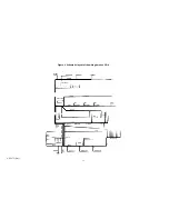
Page 33: ...Figure 4 Schematic layout of the wiring harness GO 4 AM 075 Part 33 ...

Page 34: ...wer supply PS 4 15 V M M presets PZ 4 plug 1 pin 15 V Pos supply voltage 9 W r Power supply PS 4 15 V U M presets PZ 4 plug 1 pin 15 V Pos supply voltage 10 W r Power supply PS 4 15 V Key pop H P 1 pin V Pos supply voltage 11 W r Power supply PS 4 15 V Wersivoice 11 W V 7 pin 11 Pos supply voltage 12 W r Power supply PS 4 15 V Wersivoice I WV 7 pin 11 Pos supply voltage 13 W r Power supply PS 4 15...

Page 35: ... plug t pin 1 Neg supply voltage 37 W bl Power supply PS 4 15 V Swell indicator LA 1 plug 1 pin 15 Neg supply voltage 38a W bl Power supply PS 4 15 V U M presets PZ 4 plug 1 pin 15 V Neg supply voltage 38b W bl U M presets PZ 4 plug 1 pin 15 V M M presets PZ 4 plug 1 pin 15 V Extension of 38a 38c W bl M M presets PZ 4 plug 1 pin 15 V L M presets PZ 4 plug 1 pin 15 V Extension of 38b 38d W bl L M p...

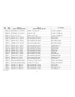
Page 36: ...e H K 13 pin 15 Neg supply voltage 59b W bl M M envelope H K 13 pin 15 M M bus bar Keying voltage 60a W bl Power supply PS 4 15 V L M envelope H K 13 pin 15 Neg supply voltage 60b W bl L M envelope H K 13 pin 15 L M bus bar Keying voltage 61 W bl Power supply PS 4 15 V Arpeggio AG 1 plug 3 pin 20 Neg supply voltage 62 W bl Power supply PS 4 15 V Pedal electr P E 36 plug 7 pin 15 N eg supply voltag...

Page 37: ...N D 87 W bk Power supply PS 4 G N D U M spec eff E F 1 pin 21 G N D 88 W bk Power supply PS4 G N D M M spec eff EF1 pin 21 G N D 89 W bk Power supply PS 4 G N D C bar of shelf G N D 90 W bk Power supply PS 4 G N D Left studio amp SV 7 pin G N D G N D 91 W b k Power supply P S 4 G N D Right studio amp SV 7 pin G N D G N D 92 VC bk Powersupply PS4 G N D Board CO 4 point36 G N Dforswellpedal 93 W bk ...

Page 38: ...23 G N D 115 not used 116 not used 117a W w bl Power supply PS 4 25 V D C Lower lamp at WE R Sllogo Unregulated D C 117b W w bl Lower lamp at WE RSllogo Upper lamp at WERSllogo Extension of 117a 117c W w bl Upper lamp at WERSllogo Stop tablet illumination Extension of 117b 118 W gn bn L M sound comp SC 3 plug 1 pin 1 L M fixed stops G P 1 plug 2 pin PM PMU L Man program control voltage 119 W gn bn...

Page 39: ...point p M Extension of 126b 126d W gn Switch bank Spec eff Sources US 1 point pM Switchbank Wah Wah US 1 point p M Extension of 126c 126e W gn Switchbank Wah Wah US1 point p M Switchbank Spec Eff Rates US1 point p M Extension of 126d 126 f W gn Switchban k Spec Eff Rates U S 1 point p M Switchbank Drawbar Presets switch U M Preset 1 point pM Extension of 126e 126g W gn Switchbank Drawbar Presets s...

Page 40: ...Wersivoice I WV 7 pin 3c LIM drawbars to Wersivoice I 137 W w bk LIM fixed stops G P t plug 1 pin F R VV Channel selectors S 4 K point 17 LIM fixed stops to ch sel 138 W ye Channel selectors S 4 K point 18 Right preamp VV 2 plug 4 pin S6 LIM fixed stops to right preamp 139 W r bl Channel selectors S 4 K point 16 Left preamp VV 2 plug 4 pin S 6 L M fixed stops to left preamp 140 W r bl LIM fixed st...

Page 41: ...voice I 149 W gn r M M fixed stops G P 1 plug 1 pin F R VV Channel selectors S 4 K point 11 M M U M Il to ch sel 150 W ye bk Channel selectors S 4 K point 12 Right preamp VV 2 plug 4 pin S4 M M U M Il to right preamp 151 W gn bk Channel selectors S 4 K point10 Left preamp V V 2 plug 4 pin S4 M M U M Il to left preamp 152 VC gn bk M M fixed stops GP1 plug1 pin F R WV Wersivoice1 WV 7 pin 2c M M U M...

Page 42: ...eamp VV 2 plug 4 pin S 2 U M fixed stops to right preamp 163 W wiye Channel selectors S 4 K point 4 Left preamp V V 2 plug 4 pin S 2 U M fixed stops to left preamp 164 W w ye U M I fixed stops G P 1 plug 1 pin F R WV Wersivoice II WV 7 pin 2c U M fixed stops to Wersivoice 11 165 S gy Pedal drawbars ZR 1 cond to pin 10 shield to pin 9 Pedal electr PE 36 plug 6 cond to pin 18 shield cut off Pedal dr...

Page 43: ...1 cond to pin 12 shield cut off 2nd harmonic audio to M M spec effects 178a S bn M M drawbar presets PZ 4 plug 1 cond to pin Outp shield to pin G N D Right preamp VV 2 plug 3 cond to pin E3 shield cut off M M drawbars audio to both preamps 178b S bn M M drawbar presets PZ 4 plug 1 cond to pin Outp shield to pin G N D Wersivoice I WV 7 cond to pin 1 shield cut off M M drawbars audio to Wersivoice I...

Page 44: ...rsivoice 11 5 pos US 1 switch Normal Soft point a Normal Soft 190 W ye Wersivoice 11 WV 7 pin 12 Switch bank Wersivoice II 5 pos US 1 switch Normal Heavy point a Normal Heavy 191 S ye Wersivoice II W V 7 cond to pin 10 shield to pin 9 Left preamp V V 2 plug 3 cond to pin E 10 shield cut off I Wersivoice II audio ic left preamp 192 W r bl Wersivoice I W V 7 pin 15 Switch bank Wersivoice 1 14 p os U...

Page 45: ...U M spec eff E F 1 pin 6 Switch Fast Rate US 1 point a Fast Rate 205 W w bk U M spec eff E F 1 pin 5 Switch Medium Rate US 1 point a Medium Rate 206 W w bl U M spec eff E F 1 pin 4 Switch Slow Rate US 1 point a Slow Rate 207 W w r U M spec eff E F 1 pin 3 Switch Variable Rate US 1 point a Variable Rate 208 W ye U M spec eff E F 1 pin 2 Master control Sp eff rate term A 209a W ye bl U M envelope H ...

Page 46: ... panel Wah Wah term S Manual Wah Wah 228a W ye M M spec eff EF 1 pin 18 Right control panel Wah Wah Speed term A 228b W ye M M spec eff EF t oin 17 Right controlpanel Wah Wah Speed terms 229a W pk M M soec eff EF 1 pin 10 Right control panel Free Run Speed term a 229b W pk M M spec eff EF 1 pin 9 Right control panel Free Run Speed term s 230 S w M M spec eff E F 1 cond to pin 8 shield to pin G N D...

Page 47: ... r M M spec eff E F 1 pin Pg 7 Right control panel SW 5 point 9 I M M fixed stops 243 W ye bn M M spec eff E F t pin Pg 6 Right control panel SW 5 point 6 M M 2nd Voice 244 W r bl M M spec eff E F 1 pin Pg 5 Right control panel SW 5 point 5 M M Tremolo 245 W pk M M spec eff E F 1 pin Pg 4 Right control panel SW 5 point 4 M M Contracussion 246 W w M M spec eff E F t pin Pg 3 Right control panel SW ...

Page 48: ...control panel Slalom control term A side 11 Slalom control 264 W gy Generator 1 G 1 plug A pin 1 Right control panel SW 5 point 29 Vibrato III Gen l 265 W w bl Generator 1 G 1 plug A pin 2 Right control panel SW 5 point 28 Vibrato 11 Gen l 266 W ye bn Generator 1 G 1 plug A pin 3 Right control panel SW 5 point 27 Slow vibrato Gen l 267 W r bl Generator 1 G 1 plug A pin 6 Right control panel SW 5 p...

Page 49: ...ug 2 pin ces Twin transp ll plug 2 pin ces 283a W w bk Transposerswitch TP point b b Twin transp l plug 2 pin b 283b i W w bk Twin transp 1 TP 2 plug 2 pin b Twin transp ll plug 2 pin b 284a W r ye Transposerswitch TP point a I Twin transp l plug 2 pin a 284b W r ye Twin transp I TP 2 plug 2 pin a Twin transp ll plug 2 pin a 285a W w bn Transposes switch TP point a b Twin transp l plug 2 pin as 28...

Page 50: ...e bn Piano PI1 plug 2 pin Pi Switch Piano US 1 point a 303 W ye bk Piano PI1 plug 2 pin Ba Switch Banjo US 1 point a 304 W ye r Piano PI1 plug 2 pin B Piano Pl13 term B Banjo control line 305 W w bn Piano PI1 plug 2 pin Ec Switch Echo US 1 pointa 306 W w r Piano PI1 plug 2 pin Tr Switch Tremolo US 1 point a 307 W w bl Piano PI1 plug 2 pin S L Switch Long Sustain US 1 point a 308 W w bk Piano PI1 p...

Page 51: ...eft preamp VV 1 plug 1 cond to pin E 13 shield to pin G Panel AP 1 G twin control cond to term SI shield to term AI Left playback volume 323 S bn Panel AP 1G twin control cond to term El shield to term AI Panel AP 1G DIN connector cond to term 3 shield cut off Left tape playback 324 S ye Left pream p V V 1 plug 1 cond to pin Al 3 shield to pin G Panel AP 1G DIN connector cond to term 1 shield cut ...

Page 52: ...ht controlpaneI SW 6 point 9 U M Soft Attack I 338 VV bn U M envelope HK 13 term Sust short Right controlpanel SW 6 point 10 U M Short Sustain 339 W gy U M envelope HK 13 term Sust med Right controlpaneI SW 6 point 11 U M Medium Sustain 340 W w I JIM envelope HK13 term Sust long Right controlpanel SW 6 point 12 U M Long Sustain 341 W pk M M envelope HK 13 term Att soft Right controlpanel SW 6 poin...

Page 53: ... pk Pedal electr P E 36 plug 5 pin 3 Right control paneI SW 6 point34 Long Sustain 359 W r bl Pedal electr P E 36 plug 5 pin 2 Right control panel SW 6 point 33 Short Sustain 360 W ye bn Pedal electr P E 36 plug 5 pin 1 Right control paneI SW 6 point 35 Pedal Drawbars 361 W bn Sweilindicator LA 1 plug 1 pin L D R Board CO 4 point 32 Swell indicator control voltage 362 W ye Key pop H P1 plug1 pin C...

Page 54: ...d stops GP 1 pin Pg 1 U M Ilfixed stops G P1 pin Pg 1 Horn 16 377 W bn U M fixed stops GP1 pin Pg 2 U M Ilfixed stops G P1 pin Pg 2 Saxophone 16 378 W bn U M Ifixedstops GP 1 pin Pg3 U M Ilfixedstops G P1 pin Pg 3 Accordion 16 379 W bn U M fixed stops GP 1 pin Pg 4 I U M Ilfixedstops G P1 pin Pg 4 Trombone 16 i 380 W bn U M I Axed stops G P 1 pin Pg 5 U M Ilfixed stops G P 1 pin Pg 5 Cello 16 381 ...

Page 55: ... controlpanel Arpeggio Speed term e Arpeggio AG 1 plug 1 pin 15 Arpeggio Speed 403 W ye bk Right control panel Arpeggio Speed terms Arpeggio AG 1 plug 1 pin 9 Arpeggio Speed 404 W gy Arpeggio control term S Arpeggio AG 1 plug 1 pin 2 Slide control 405 W w bl Arpeggio control term A Arpeggio AG 1 plug 1 pin 3 Slide control 406 W w bk Arpeggio controkterrn F Arpeggio AG 1 plug 1 pin 4 Slide control ...

Page 56: ...int 19 M M sound comp SC 5 plug 2 pin 16 M M Address A 2 427 W ye bk Left control panel SW 3 point 20 M M sound comp SC 5 plug 2 pin 17 M M Address A 1 428 W ye bk Left control paneI SW 3 point21 M M sound camp SC 5 plug 2 pin 18 M M Address A0 429 W w bk Left control panel SW 3 point10 U M sound comp SC 5 plug Z pin 14 U M Address A4 430 W w bk Left control paneI SW 3 point16 U M sound comp SC 5 ...

Reviews: