


- 50 -
9.13.1
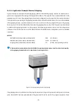
Application Example External Gripping
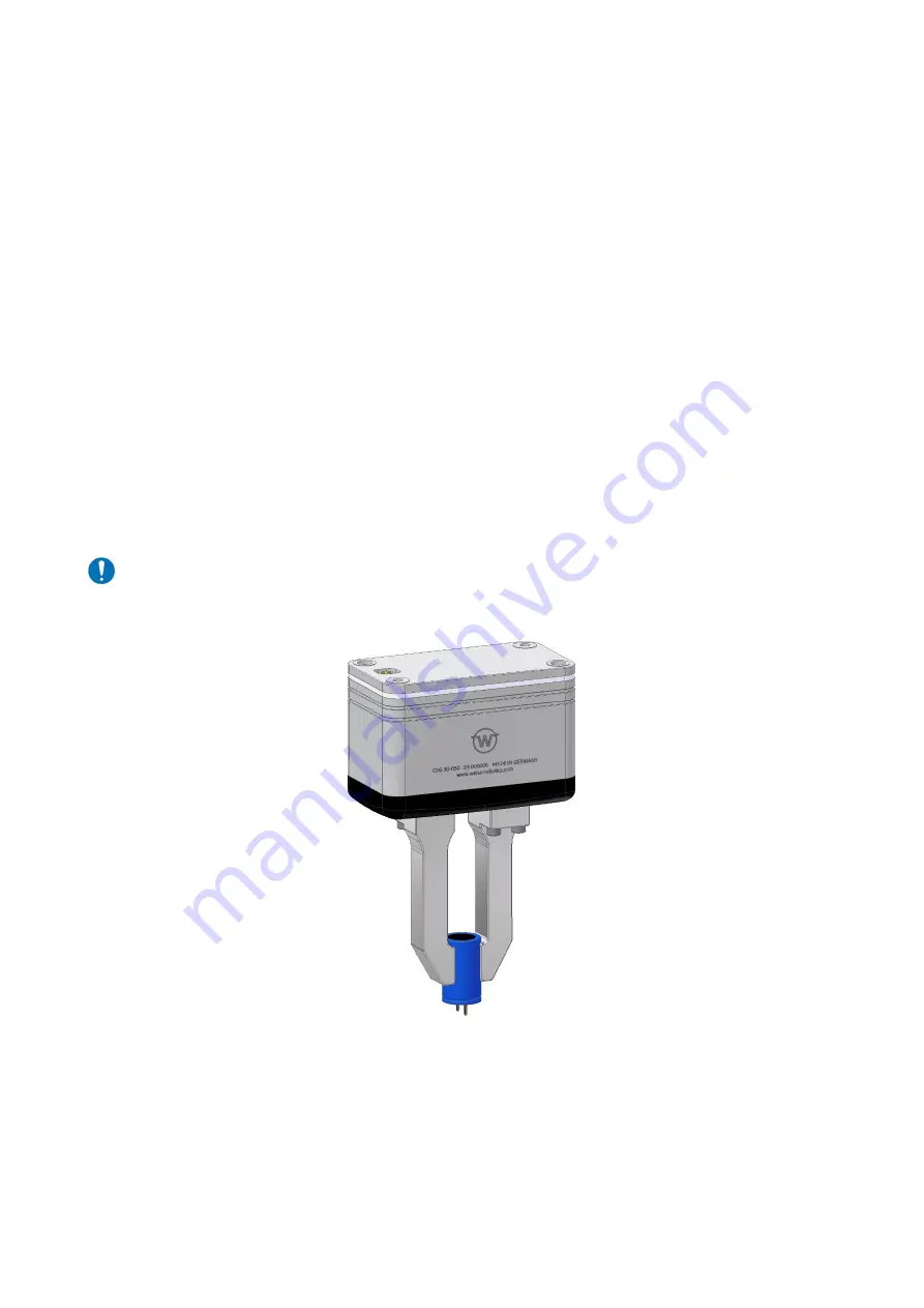
Figure 19 shows an example of external gripping with the CRG 30-050 gripping module. An electrolytic ca-
pacitor is to be gripped at the casing and dropped into a fixture. The capacitor has a nominal diameter in the
gripping area of 15 mm. The gripping fingers have been configured in such a way that the nominal diameter
corresponds to a jaw spacing at the gripping module of 10 mm (half the total stroke). To ensure the reliability
of the gripping process, a position tolerance of ± 1 mm is set. Due to the low weight of the part, the gripping
force is set to 21 N. For the CRG 30-050, this means the gripping force is set to 70%. The part is parameterized
as GRIP 0 of the gripping module. For this purpose, the following parameters are set via the configuration
software of the IO-Link master or via the Weiss Robotics DC-IOLINK device configurator, which is available
separately:
GRIP 0:
NO PART Limit (index 0x60, subindex 0x01):
900
(= 9.00 mm)
RELEASE Limit (index 0x60, subindex 0x02):
1100 (= 11.00 mm)
Gripping force (index 0x60, subindex 0x03):
70
(= 70%, corresponding to 21 N)
If the module is parameterized via DC-IOLINK, the parameterized values must be stored remanently
in the gripping module before it is deactivated, see chapter 8.2.1.
Figure 19: Gripping example external gripping
The gripping process is performed via the program sequences in Figure 15 (grip part) and Figure 16. (release
part). Since GRIP 0 has been parameterized, the grip index 0 must be used in the program sequence. 0 was


