Digital and Analog Inputs and Outputs
CFW300 | 12-7
12
P251 - AO1 Function
P254 - AO2 Function
Adjustable
Range:
0 = Speed Ref.
1 = Not Used
2 = Real Speed
3 and 4 = Not Used
5 = Output Current
6 = Not Used
7 = Active Current
8 to 10 = Not Used
11 = Motor Torque
12 = SoftPLC
13 to 15 = Not Used
16 = Motor Ixt
17 = Not Used
18 = Content of P696
19 = Content of P697
20 = Not Used
21 = Application Function 1
22 = Application Function 2
23 = Application Function 3
24 = Application Function 4
25 = Application Function 5
26 = Application Function 6
27 = Application Function 7
28 = Application Function 8
29 = Control Setpoint (PID Controller Application)
30 = Process Variable (PID Controller Application)
Factory
Setting:
P251 = 2
P254 = 5
Properties:
Description:
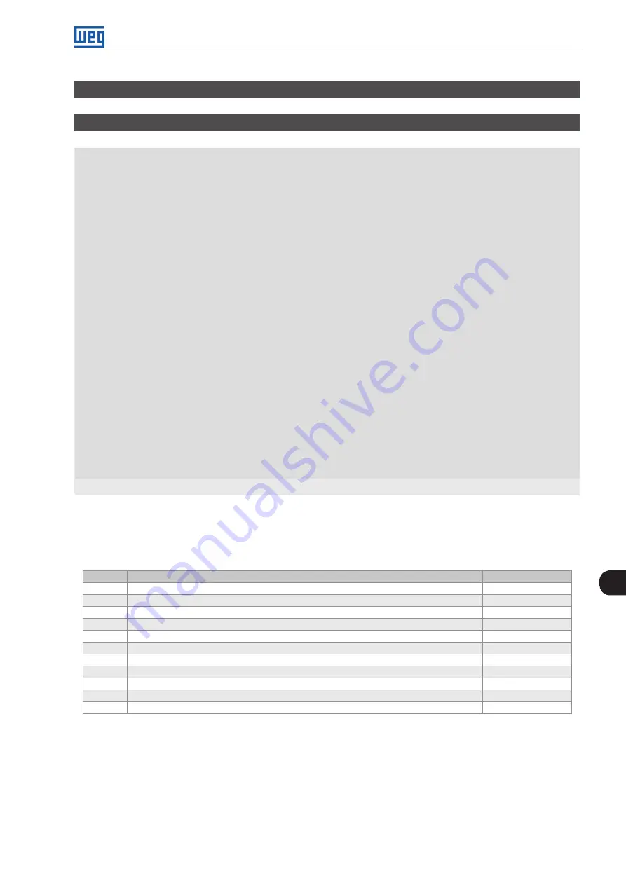
These parameters sets the functions of the analog outputs, according to function and scale presented in
Table 12.3:
Full scale of the analog output
Function
Description
Full Scale
0
Speed reference at the input of the ramp P001
P134
2
Effective speed at the inverter output
P134
5
Total output current RMS
2 x P295
7
Active current
2 x P295
11
Torque on the motor in relation to the rated torque
200.0 %
12
SoftPLC scale for analog output
32767
16
Ixt overload of the motor (P037)
100 %
18
Value of P696 for analog output AOx
32767
19
Value of P697 for analog output AOx
32767
29
Control Setpoint (PID Controller Application)
(*)
30
Process Variable (PID Controller Application)
(*)
(*)
For further details refer the
Summary of Contents for CFW300 V1.3X
Page 2: ......
Page 8: ...Contents...
Page 46: ...Identification of the Inverter Model and Accessories 6 4 CFW300 6...
Page 60: ...Logical Command and Speed Reference 7 14 CFW300 7...
Page 72: ...V f Scalar Control 9 10 CFW300 9...
Page 80: ...VVW Vector Control 10 8 CFW300 10...
Page 116: ...Digital and Analog Inputs and Outputs 12 24 CFW300 12...
Page 132: ...Reading Parameters 15 6 CFW300 15...


