SoftPLC
CFW300 | 18-1
18
18 APPLICATIONS
18.1 INTRODUCTION
Using the SoftPLC function of the CFW300, it is possible to develop an application (or functionality) in ladder
language and include it in the CFW300 inverter software.
Parameter P903 allows selecting the application and uploading it to the SoftPLC execution area of the CFW300.
The CFW300 has the following application already implanted:
PID controller
18.2 PID CONTROLLER
The PID controller application can be used to control a process in closed loop. This application adds a proportional,
integral and derivative controller superimposed to the regular speed control of the CFW300. It enables the selection
of the control setpoint source and process variable source, the selection of operation in manual or automatic mode,
alarms by low or high process variable level, the configuration of the control action in direct or reverse mode, and
also the possibility of setting the conditions to activate the sleep and wake up mode.
Basically, the PID controller application compares the control setpoint to the process variable and controls the
motor speed to try to eliminate any errors so as to keep the process variable equal to the control setpoint required
by the user. The setting of the gains P, I and D determine the speed at which the inverter will respond to eliminate
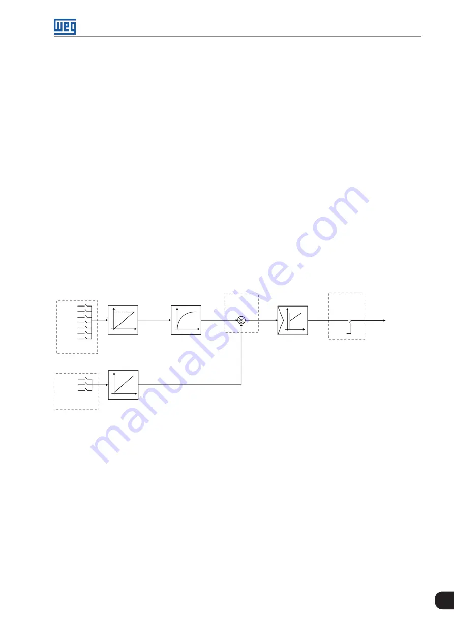
that error. See the PID controller block diagram below.
P922, P923
Process variable
Selection via
P920
Selection
via P921
Control
setpoint
P911
P916
AI1
AI1
AI2
AI2
AI1 - AI2
P911
P912
P913
P914
P915
P917
P918
P935
Filter for control
setpoint
PID
controller
P931, P932
P933, P934
Control
action via
P928
Operation
mode via
P929
Speed
reference
0.0 % (P133)
to 100.0 %
(P134)
(-) (+)
T
A
M
Figure 18.1:
PID controller block diagram
Application examples of the PID controller:
Flow or pressure control in a pipe system.
Temperature of a furnace or oven.
Dosing of chemicals in tanks.
The example below defines the terms used by the PID controller application.
An electric pump used in a water pumping system in which the pressure must be controlled at the pump output
pipe. A pressure transducer is installed on the pipe and provides an analog feedback signal to the CFW300
proportional to the water pressure. That signal is called process variable and can be viewed in parameter P916.
A control setpoint is programmed in the CFW300 via HMI (P911), or via analog input (AI1 or AI2), or via electronic
potentiometer function (DI3 and DI4), or via logical combination of digital inputs DI3 and DI4 according to the
control setpoint source defined in P920. The control setpoint is the water pressure which the pump must produce
regardless of the demand variations in the pump output at any moment.
Summary of Contents for CFW300 V1.3X
Page 2: ......
Page 8: ...Contents...
Page 46: ...Identification of the Inverter Model and Accessories 6 4 CFW300 6...
Page 60: ...Logical Command and Speed Reference 7 14 CFW300 7...
Page 72: ...V f Scalar Control 9 10 CFW300 9...
Page 80: ...VVW Vector Control 10 8 CFW300 10...
Page 116: ...Digital and Analog Inputs and Outputs 12 24 CFW300 12...
Page 132: ...Reading Parameters 15 6 CFW300 15...


