background image

10

5.3 Calibration Error

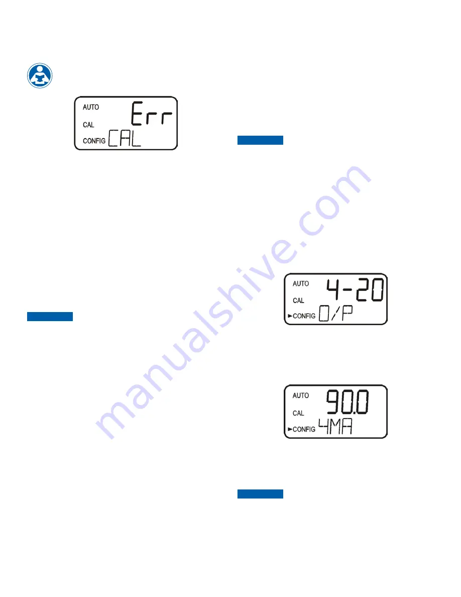
If the screen shown below is displayed after the 100%T or 0 ABS 

calibration, the internal diagnostics have determined that the calibration 

fluid requires replacement or the flow through cuvette requires 

replacement. Check, the calibration fluid and cuvette, then 

recalibrate or restore the factory calibration see 

6.1 Restoring 

Factory Settings

. The instrument cannot be used without 

performing one of these operations.

To recalibrate press the MODE key and start the calibration sequence 

again. To restore the factory calibration, push and hold the 

 button. 

Now push and release the 

  then release the 

 button.

6.0 Restore Factory Settings

6.1 Restoring Factory Settings

If the instrument is unable to perform a calibration due to a low lamp 

output, bad calibration standard or a dirty cuvette, the instrument will 

display 

CAL

 on the lower row of the display and 

Err

 on the upper 

row. The operator has two choices to correct this problem or restore 

the factory calibration. If the operator can determine whether a poor 

calibration or a low lamp caused the problem, he/she can remedy 

the problem and recalibrate. If all else fails, the operator may restore 

the factory calibration and configuration settings by performing the 

following operation. Push and hold the 

 button. Now push and 

release the 

  then release the 

 button. Factory calibration and 

factory configuration have now been restored.

Restoring the factory settings allows the use of the AccUView 

LED with reduced accuracy. The original problem still exists and 

must be determined and corrected before accurate operation 

of the AccUView LED will be resumed. The AccUView LED will 

always reset to %T and factory defaults after restoring.

NOTICE

7.0  Instrument Configuration 

(CONFIG mode)

The instrument has been designed to provide the ability to customize 

the instrument according to needs at any time during normal operation. 

This mode has been split into sub-menus to facilitate instrument 

configuration. This section describes how to use each of the sub-

menus to configure the instrument. While in the configuration mode, 

the instrument has a time-out feature that automatically returns the 

system operation to the 

AUTO

 mode after a fifteen (15) minute period.

Enter the 

CONFIG

 mode of the instrument by pressing the 

MODE/EXIT 

button

 until the arrow beside CONFIG is illuminated, then press  

the 

  button.

To exit the CONFIG mode, press the MODE/EXIT button.

NOTICE

7.1 Selecting the Output (O/P)

The first configuration selection is the O/P. The selections are:
1.   

4-20

 for the 4-20 mA output

2.   

485

 for the RS-485 and modbus

3.   

OFF

 if no outputs are required

Select the desired output by using the 

 and 

 buttons. Once the 

desired output has been set, press the 

  button to accept it. The next 

prompts will depend on the output selected.

7.2 Setting the 4-20 mA

If the 4-20 mA output was turned on, prompts to set the 4mA 

(4MA)

 and 

20mA 

(20MA)

 %T or ABS limits levels will be displayed. There is also a 

menu to adjust the error level 

(ERLV)

. The first prompt will be the %T or 

ABS limit assigned to the 4 mA output level.

7.2.1 Setting the 4 mA Level 

Select the %T or ABS level to assign to the 4MA using the 

 and 


buttons.

The factory setting is 90%T or.

Once the desired level has been set, press the 

  button to accept it.

The factory default setting for %T is 90%T and the for ABS is 0

The 4MA cannot be set higher than the 20 MA level.

NOTICE

Summary of Contents for HF scientific AccUView LED

Page 1: ...e Monitor IS HF AccUViewLED WARNING Read this Manual BEFORE using this equipment Failure to read and follow all safety and use information can result in death serious personal injury property damage o...

Page 2: ...d and passed EN 61326 1 2013 Manufacturer s Name HF scientific inc Manufacturer s Address 16260 Airport Park Drive Suite 140 Fort Myers Florida 33913 Importer s Name Importer s Address Type of Equipme...

Page 3: ...etting the Error Level 11 7 3 Configuring the RS 485 Port 11 7 3 1 Setting the Baud Rate 11 7 3 2 Setting the Address 11 7 4 Configuring the Alarms 11 7 4 1 Alarm 1 12 7 4 2 Alarm 2 12 7 5 Enabling th...

Page 4: ...indicates the items in the monitor shipment Item Quantity AccUView LED Monitor c w Field Terminal Box and Flow Through Assembly 1 Instruction Manual 1 Desiccant Pack 1 Quartz Cuvette with Ultrasonic...

Page 5: ...recommended mounting screws are M6 for the instrument enclosure and M4 3 16 for the field terminal box The AccUView LED is designed to have the field terminal box cradled under the sensor portion of...

Page 6: ...Model 28042 is equipped with a flow switch For this instrument the user connections are equipped with push to connect connections The suitable tubing is polymer or copper tubing with a inch OD These c...

Page 7: ...e While making connections refer to Figure 5 The AccUView LED is not supplied with a power cord 3 3 2 RS 485 The RS 485 Modbus or special protocol half duplex 2 wire digital interface operates with di...

Page 8: ...or the digital output depending on the options selected A flashing display may occur after warm up This is an indication that either the ambient or the water temperature or has changed rapidly During...

Page 9: ...e calibration 7 The upper display will count down the progress of the calibration step 8 The instrument will return to AUTO mode at the end the calibration 9 The shutoff clamp should now be released t...

Page 10: ...n of the AccUView LED will be resumed The AccUView LED will always reset to T and factory defaults after restoring NOTICE 7 0 Instrument Configuration CONFIG mode The instrument has been designed to p...

Page 11: ...rm 1 The alarm function HI LO OFF or Error 2 The alarm set point level at which the alarm activates 3 The delay time for the alarm the time that the set point must be exceeded prior to alarm activatio...

Page 12: ...tionalities is selected a prompt to set the delay times and the set point as with Alarm 1 will be displayed 7 5 Enabling the Security Access The instrument is equipped with a security access If this o...

Page 13: ...The factory 6 second update will extend the LED life to over 5 years The 60 second setting increases LED life to about 14 years but this will delay all updates Change the selected update period using...

Page 14: ...ust be used for the system to operate correctly The system works by sending an ultrasonic frequency through spring connections into a piezo transducer bonded to the bottom of a flow through cuvette Th...

Page 15: ...ed shutoff clamp unscrewing the old cuvette and replacing with a fresh clean one Recalibration will be required for accurate operation 9 2 Replacing or Installing the Desiccant Pouch The AccUView LED...

Page 16: ...the fault will be shown on the lower row of the display 10 2 System FAIL Message Normally this condition indicates that the instrument will require servicing Contact either the HF scientific Technica...

Page 17: ...ly 28474 AccUView LED Version with Flow Alarm Factory Installed Provides an alarm if sample flow is interrupted 28042 Tubing Kit Containing 1 shutoff clamp 1 backpressure valve 2 connecting tubings wi...

Page 18: ...3 500 87 33 3 438 30 17 1 188 147 66 5 813 Note 1 See the mounting instructions in the manual for mounting hardware sizes 2 Provide at least 200mm 8 inches of free space above the sensor for easy rem...

Page 19: ..._ _ _ _ _ _ _ _ _ _ _ _ _ _ _ _ _ _ _ _ _ _ _ _ _ _ _ _ _ _ _ _ _ _ _ _ _ _ _ _ _ _ _ _ _ _ _ _ _ _ _ _ _ _ _ _ _ _ _ _ _ _ _ _ _ _ _ _ _ _ _ _ _ _ _ _ _ _ _ _ _ _ _ _ _ _ _ _ _ _ _ _ _ _ _ _ _ _ _ _...

Page 20: ...ompany shall not be responsible for any incidental special or consequential damages including without limitation lost profits or the cost of repairing or replacing other property which is damaged if t...

Reviews: