


Benchmark 750-3000 Installation & Startup Manual
SECTION 6
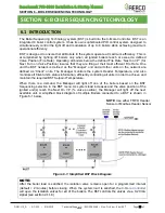
– BOILER SEQUENCING TECHNOLOGY
OMM-115_D
•
GF-200
•
5/9/2019
Technical Support
•
(800) 526-0288
•
Mon-Fri, 8 am - 5 pm EST Page 100 of
126
6.1.1 INSTALLATION NOTES
If you are installing a BST system that also includes a ProtoNode SSD (Client-Client Device),
you
must
adhere to the procedure listed below. Failure to complete these steps can result in the
failure of the BST system.
a)
Do
NOT
install the ProtoNode device at the outset of the installation. If the ProtoNode
Device is already installed, you must physically disconnect it from the Modbus network in
I/O board.
b)
Make sure that the Modbus load and bias resistors are properly configured for the system
to operate without the ProtoNode installed.
c)
Temporarily set the BST system for CONSTANT SETPOINT mode of operation (see
below).
d)
Turn on and completely test the installation to verify that it is operating proper.
e)
Once the installation is working properly as a BST system, install the ProtoNode device.
f)
Make sure that the Modbus load and bias resistors are properly configured for the system
to operate with the ProtoNode installed.
g)
Set the BST system for desired mode of operation (SETPOINT mode).
h)
Test the system completely with the ProtoNode installed.
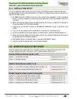
6.2 AERCO BST QUICK START CHART
Select the single option that suites your installation and then complete the instructions in the
corresponding sub-sections of section 6.3
BST Implementation Instructions
.
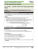
Constant Setpoint (choose option 1 or 2)
Option 1
– Direct Wired Header
Complete section 6.3.1
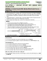
Option 2
– Modbus Header
Complete section 6.3.2
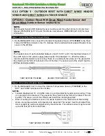
Outdoor Reset (choose option 3 or 4)
Option 3
– Direct Wired Header AND Direct Wired Outdoor Air
Complete section 6.3.3
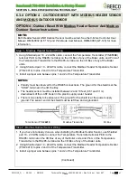
Option 4
– Modbus Header AND Modbus Outdoor Air
Complete section 6.3.4
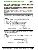
Remote Setpoint (choose option 5 through 8)
Option 5
– 4-20ma Drive AND Direct Wired Header
Complete section 6.3.5
Option 6
– Modbus Drive AND Direct Wired Header
Complete section 6.3.6
Option 7
– 4-20ma Drive AND Modbus Header
Complete section 6.3.7
Option 8
– Modbus Drive AND Modbus Header
Complete section 6.3.8


