


Benchmark 750-3000 Installation & Startup Manual
SECTION 3 - START SEQUENCE
OMM-115_D
•
GF-200
•
5/9/2019
Technical Support
•
(800) 526-0288
•
Mon-Fri, 8 am - 5 pm EST Page 48 of
126
Start Sequence:
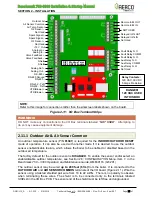
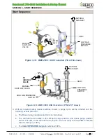
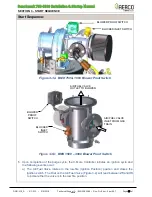
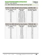
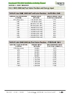
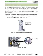
Figure 3-2a: BMK 750 & 1000 Air/Fuel Valve in Purge Position
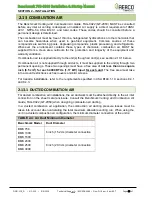
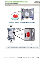
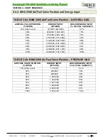
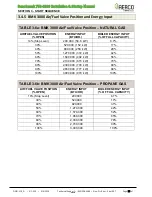
Figure 3-2b: BMK 1500
– 3000 Air/Fuel Valve In Purge Position
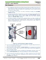
4. Next, the blower proof switch on the Air/Fuel Valve (Figure 3-3a and 3-3b) closes. The
display will show
PURGING
and indicate the elapsed time of the purge cycle in seconds.
TO BLOWER
STEPPER
MOTOR
AIR IN
PURGE
VALVE POSITION
DIAL AT 100%
STEPPER MOTOR
TO
BLOWER
AIR INLET
100


