background image

Benchmark 750-3000 Installation & Startup Manual


SECTION 2 

– INSTALLATION 


OMM-115_D


•  

  GF-200    

•  

  5/9/2019               

Technical Support


  (800) 526-0288  

  Mon-Fri, 8 am - 5 pm EST             Page 22  of 

126 


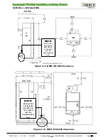
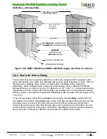
Figure 2-4b: BMK 1500/2000 and BMK 2500/3000 Supply and Return Locations 


2.6.3  Dual Inlet Return Piping 

The standard dual inlet connections


allow these units to be configured with a separate cooler 

return temperature zone, rather than blending high and low return temperature zones.  Utilizing 
the dual return capability, these boilers can take further advantage of the condensing 
capabilities.  When configured with a lower return temperature zone or AERCO SmartPlate, 
thermal efficiency can improve by up to 6% (Based on an 80 °F (26.7 °C) minimum return water 
temperature at full fire. Lower return temperatures are possible which would yield even greater 
efficiency gains.  The maximum temperature differential across the boiler heat exchanger is 100 
°F (37.8 °C). 

To use the secondary inlet, pipe the 

warmer

 return water to the 

secondary

 (upper) inlet and 

the 

cooler

 return water to the 

primary

 (lower) inlet. If the flow through both the primary and the 

secondary return is constant, then the combined minimum flows must equal the specified 
minimum flow of the boiler. If the flow through either of the inlet returns is intermittent, then the 
minimum flow through one of the return connections must always equal the specified minimum 
flow of the boiler. Contact your AERCO representative for additional information. 


CONDENSATE DRAIN 

HOT WATER  
OUTLET 
(SUPPLY) 

SECONDARY

  WATER INLET  

(

WARMER

 WATER RETURN) 


AIR INLET 

PRIMARY


WATER INLET 

(

COOLER

 WATER 

RETURN) 

EXHAUST MANIFOLD 

BMK 1500/2000


BMK 2500/3000


2” NATURAL GAS OR 

1” PROPANE INLET  

Summary of Contents for Aerco Benchmark OMM-0116

Page 1: ...ark Power Guide Applies to serial numbers G 19 0001 and above Disclaimer The information contained in this manual is subject to change without notice from AERCO International Inc AERCO makes no warran...

Page 2: ...750 1000 Supply and Return Piping 21 2 6 2 BMK 1500 3000 Supply and Return Piping 21 2 6 3 Dual Inlet Return Piping 22 2 7 PRESSURE RELIEF VALVE INSTALLATION 23 2 8 CONDENSATE DRAIN AND PIPING 24 2 9...

Page 3: ...AL START UP 57 4 1 INITIAL START UP REQUIREMENTS 57 4 2 TOOLS INSTRUMENTS FOR COMBUSTION CALIBRATION 57 4 2 1 Required Tools Instrumentation 57 4 2 2 Installing Gas Supply Manometer 58 4 2 3 Accessing...

Page 4: ...STANT SETPOINT WITH DIRECT WIRED HEADER SENSOR 101 6 3 2 OPTION 2 CONSTANT SETPOINT WITH MODBUS WIRED HEADER SENSOR 102 6 3 3 OPTION 3 OUTDOOR RESET WITH DIRECT WIRED HEADER SENSOR AND DIRECT WIRED OU...

Page 5: ...kW 1 000 000 293 kW 48 300 14 2 kW 968 000 284 kW BMK 1500 75 000 22 kW 1 500 000 440 kW 64 500 18 9 kW 1 395 000 409 kW BMK 2000 100 000 29 3 kW 2 000 000 586 kW 86 000 25 2 kW 1 860 000 545 kW BMK 2...

Page 6: ...r second unless each symbol is 1 bit long BMK Benchmark AERCO s Benchmark series boilers BMS or BMS II AERCO Boiler Management Systems BLDG Bldg Building BST AERCO on board Boiler Sequencing Technolog...

Page 7: ...currently used on Benchmark Innovation and KC1000 Series products IP Internet Protocol ISO International Organization for Standardization Lbs Pounds 1 lb 0 45 kg LED Light Emitting Diode LN Low Nitrog...

Page 8: ...andard for serial full duplex FDX transmission of data based on the RS422 Standard RS485 or EIA 485 A standard for serial half duplex HDX transmission of data based on the RS485 Standard RTN Rtn Retur...

Page 9: ...nstaller and kept in a safe place for future reference WARNING Do not use matches candles flames or other sources of ignition to check for gas leaks Fluids under pressure may cause injury to personnel...

Page 10: ...lers in a location other than a boiler room provide a manually operated remote shutdown switch or circuit breaker marked for easy identification at a location readily accessible in the event of boiler...

Page 11: ...the floor level where the gas equipment is to be installed In addition the installing plumber or gasfitter shall observe that a battery operated or hard wired carbon monoxide detector with an alarm i...

Page 12: ...or venting system components with the equipment the instructions provided by the manufacturer for installation of the equipment and the venting system shall include 1 Detailed instructions for the ins...

Page 13: ...t from the FRONT ONLY NOTE AERCO is not responsible for lost or damaged freight Each unit has a Tip N Tell indicator on the outside of the crate This indicates if the unit has been turned on its side...

Page 14: ...w for all models However if Local Building Codes require additional clearances these codes shall supersede AERCO s requirements The minimum acceptable clearances required are as follows Sides 24 inche...

Page 15: ...cal Support 800 526 0288 Mon Fri 8 am 5 pm EST Page 15 of 126 Figure 2 1a BMK 750 1000 Clearances Figure 2 1b BMK 1500 2000 Clearances NOTE Ensure that condensate assembly is not located over the hous...

Page 16: ...r and free from all combustible materials and flammable vapors or liquids FOR MASSACHUSETTS ONLY For Massachusetts installations the unit must be installed by a plumber or gas fitter licensed within t...

Page 17: ...el housekeeping pad to ensure proper condensate drainage The pad thickness must be BMK 750 1000 4 to 6 inch 10 2 to 15 2 cm BMK 1500 3000 4 to 8 inch 10 2 to 20 3 cm If anchoring the unit refer to the...

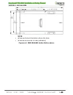
Page 18: ...ION OMM 115_D GF 200 5 9 2019 Technical Support 800 526 0288 Mon Fri 8 am 5 pm EST Page 18 of 126 NOTES All holes are flush with the bottom surface of the frame All dimensions shown are in inches mill...

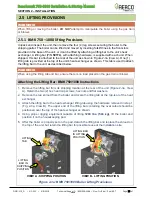
Page 19: ...elow WARNING When using the lifting tab and bar ensure there is no load placed on the gas train or blower Attaching the Lifting Bar BMK 750 1000 Instructions 1 Remove the lifting bar from its shipping...

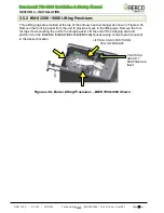
Page 20: ...xchanger as shown in Figure 2 3b Remove the front top panel from the unit to provide access to the lifting lugs Remove the four 4 lag screws securing the unit to the shipping skid Lift the unit off th...

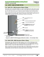
Page 21: ...se Teflon tape Figure 2 4a BMK 750 1000 Supply and Return Locations Two Inlet Option Shown 2 6 2 BMK 1500 3000 Supply and Return Piping All Benchmark 1500 2000 2500 and 3000 units have one 4 10 2 cm 1...

Page 22: ...fire Lower return temperatures are possible which would yield even greater efficiency gains The maximum temperature differential across the boiler heat exchanger is 100 F 37 8 C To use the secondary...

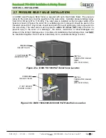
Page 23: ...sed on the threaded connections Any excess should be wiped off to avoid getting any joint compound into the valve body The relief valve must be piped to within 12 inches 30 5 cm of the floor to preven...

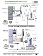
Page 24: ...l with or lower than the exhaust manifold drain port The base of the condensate trap must be supported to ensure that it is level horizontal The trap must be removable for routine maintenance AERCO re...

Page 25: ...441 1 DIAM HOSE NOTE HOUSEKEEPING PAD MUST NOT EXTEND UNDER THE CONDENSATE ASSEMBLY 3 4 NPT NIPPLES UNION EXHAUST MANIFOLD T O FLOOR DRAIN TRAP INLET INTEGRAL ADAPTOR AND THUMBSCREW TOP COVER THUMB SC...

Page 26: ...f the unit Benchmark 1500 2000 2500 3000 Features a 2 inch 5 08 cm NATURAL GAS gas inlet connection on the top of the unit Benchmark 1500P 2000P 2500P and 3000P Propane Features a 1 inch 2 54 cm PROPA...

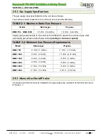
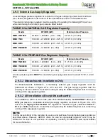
Page 27: ...kPa 14 W C 3 49 kPa Supply piping and pressure to the unit must be sufficient to provide the volume of gas while maintaining gas pressure listed below while operating at maximum capacity TABLE 2 2 Min...

Page 28: ...Pa BMK 2500 3000 150 000 3 180 000 44 932 4 0 W C 1 0 kPa A lock up style regulator MUST be used when gas supply pressure will exceed 14 W C 3 49 kPa 2 9 3 1 Massachusetts Installations Only For Massa...

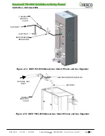
Page 29: ...0288 Mon Fri 8 am 5 pm EST Page 29 of 126 Figure 2 7a BMK 750 1000 Manual Gas Shut Off Valve and Gas Regulator Figure 2 7b BMK 1500 3000 Manual Gas Shut Off Valve and Gas Regulator 1 MANUAL SHUTOFF V...

Page 30: ...installed on the electrical supply line in an easily accessible location to quickly and safely disconnect electrical service DO NOT attach the switch to sheet metal enclosures of the unit After placin...

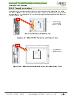
Page 31: ...he Power Box on the front of the unit Remove the front panel to access the Power Box which is mounted in the upper part of the unit as shown in Figure 2 8a and 2 8b The internal connections inside the...

Page 32: ...2 9a 2 9b and 2 9c does NOT remove power from the terminal blocks Figure 2 9a BMK 750 1000 Power Box Internal Components Figure 2 9b BMK 1500 2000 Power Box Internal Components 12V POWER SUPPLY FUSE...

Page 33: ...eption of the transformer shown in Figure 2 9a 2 9b and 2 9c all of the components in the Power Box are mounted on a DIN rail All electrical conduit and hardware must be installed so that it does not...

Page 34: ...Output I O board located behind the removable front panel assembly of the unit The location of the I O board is shown in Figure 2 10 The I O board terminal strip connections are shown in Figure 2 11...

Page 35: ...ir Sensor Common An outdoor temperature sensor P N 61047 is required for the INDOOR OUTDOOR RESET mode of operation It can also be used with another mode if it is desired to use the outdoor sensor ena...

Page 36: ...rmer P N 65085 See Section 5 12 in the Benchmark 750 3000 Operation and Maintenance Guide OMM 0116 GF 201 for more information If the current is insufficient too high or low during the ignition sequen...

Page 37: ...unit Shields must only be connected to these terminals 2 11 8 ANALOG OUT On current model Benchmark units the default setting in the C More Controller is Valve Position 0 10v and behaves as follows 0...

Page 38: ...implemented the other end of that cable is connected to the sequencing valve If BST is NOT implemented the second use is typically in conjunction with the AUXILIARY RELAY CONTACTS described in section...

Page 39: ...foot 0 64 cm per 0 3 m to avoid any condensate pooling and to allow for proper drainage While there is a positive flue pressure during operation the combined pressure drop of vent and combustion air...

Page 40: ...ee section 2 13 1 below If combustion air is not supplied through air ducts it must be supplied to the unit s through two permanent openings These two openings must have a free area of not less than o...

Page 41: ...motorized valve as the boiler cycles on and off on demand The Pump Delay Timer feature allows the user to keep the pump running and keep the motorized valve open for up to 30 minutes after the boiler...

Page 42: ...e boiler array is maximized When operated with the BST system the Manager controls its own isolation valve and sends signals to the Client units to open or close their isolation valves After the boile...

Page 43: ...ce Guide OMM 0116 GF 201 Sequencing Isolation Valve Installation Instructions 1 Install the sequencing isolation valve in the boiler s hot water outlet pipe Figure 2 15 Figure 2 15 Sequencing Isolatio...

Page 44: ...Benchmark 750 3000 Installation Startup Manual SECTION 2 INSTALLATION OMM 115_D GF 200 5 9 2019 Technical Support 800 526 0288 Mon Fri 8 am 5 pm EST Page 44 of 126 This page intentionally blank...

Page 45: ...ithout a full water level can seriously damage the unit and may result in injury to personnel or property damage This situation will void any warranty CAUTION All of the installation procedures in Sec...

Page 46: ...light 2 The unit checks to ensure that the Proof of Closure POC switch in the downstream Safety Shut Off Valve SSOV is closed See Figure 3 1a through 3 1d for SSOV location Figure 3 1a BMK 750 1000 SS...

Page 47: ...will be initiated and the following events will occur a The Blower relay energizes and turns on the blower b The Air Fuel Valve rotates to the full open purge position and closes purge position switch...

Page 48: ...re 3 2a BMK 750 1000 Air Fuel Valve in Purge Position Figure 3 2b BMK 1500 3000 Air Fuel Valve In Purge Position 4 Next the blower proof switch on the Air Fuel Valve Figure 3 3a and 3 3b closes The di...

Page 49: ...etion of the purge cycle the C More Controller initiates an ignition cycle and the following events occur a The Air Fuel Valve rotates to the low fire Ignition Position position and closes the ignitio...

Page 50: ...he IGNITION TRIAL the C More Controller will abort the Ignition Cycle and shut down the boiler Refer to Section 6 Troubleshooting Guide in the Benchmark 750 3000 Operation and Maintenance Guide OMM 01...

Page 51: ...These levels are Factory preset as follows TABLE 3 1a Start Stop Levels NATURAL GAS BMK 750 BMK 1000 BMK 1500 BMK 2000 BMK 2500 BMK 3000 Start Level 22 22 24 24 24 20 Stop Level 18 18 16 18 16 14 TABL...

Page 52: ...246 000 72 1 kW 297 000 87 0 kW 33 30 50 369 000 108 1 kW 443 000 126 9 kW 49 44 60 465 000 136 3 kW 564 000 165 3 kW 62 56 70 554 000 162 4 kW 660 000 193 4 kW 74 66 80 637 000 186 7 kW 789 000 231 2...

Page 53: ...Level 76 000 22 3 kW 5 0 20 127 000 37 2 kW 8 5 30 366 000 107 2 kW 24 4 40 629 000 184 3 kW 41 9 50 822 000 240 9 kW 54 7 60 977 000 286 2 kW 65 0 70 1 119 000 327 9 kW 74 5 80 1 255 000 367 7 kW 83...

Page 54: ...op Level 100 000 29 3 kW 5 7 20 143 000 41 9 kW 11 30 388 000 113 7 kW 23 40 759 000 222 4 kW 37 50 1 069 000 313 2 kW 51 60 1 283 000 375 9 kW 61 70 1 476 000 432 5 kW 74 80 1 675 000 490 1 kW 83 90...

Page 55: ...T OF FULL CAPACITY 16 Stop Level 167 000 48 9 kW 6 7 30 430 000 126 0 kW 17 40 770 000 225 7 kW 31 50 1 070 000 313 6 kW 43 60 1 440 000 422 0 kW 58 70 1 815 000 531 9 kW 73 80 2 030 000 594 9 kW 81 9...

Page 56: ...RGY INPUT OF FULL CAPACITY 14 Stop Level 200 000 58 6 kW 6 7 30 520 000 152 kW 17 40 880 000 258 kW 29 50 1 270 000 372 kW 42 60 1 680 000 492 kW 56 70 2 100 000 615 kW 70 80 2 390 000 700 kW 80 90 2...

Page 57: ...factory trained start up and service personnel After performing the start up procedures below it will be necessary to perform the procedures in Section 5 Safety Device Testing below to complete all i...

Page 58: ...he SSOV during Combustion Calibration in Section 4 4 below install the 16 W C 4 0 kPa manometer s as described in the following steps Gas Supply Manometer Installation Instructions 1 Turn off the main...

Page 59: ...K 2500 1 4 Inch Gas Plug Location P N 22190 shown NATURAL GAS INLET SSOV TO AIR FUEL VALVE LEAK DETECTION BALL VALVE 1 4 NPT PLUG Install manometer here for Combustion Calibration HIGH GAS PRESSURE SW...

Page 60: ...ure 4 2a and 4 2b Prepare the port for the combustion analyzer probe as follows Analyzer Probe Port Access Instructions 1 Refer to Figure 4 2a or 4 2b and remove the 1 4 NPT plug from the exhaust mani...

Page 61: ...installer operator to switch between natural gas and propane gas onsite as needed Both fuel types require different combustion calibration values and so care should be taken to ensure the appropriate...

Page 62: ...of initial start up is necessary due to changes in the local altitude gas BTU content gas supply piping and supply regulators Combustion Calibration Test Data sheets are shipped with each unit These s...

Page 63: ...is attached and functioning properly 9 Set the ON OFF switch to the ON position 10 Press the MENU key on the front panel of the C More Controller until COMBUSTION CAL MENU appears on the display 11 P...

Page 64: ...at the nitrogen oxide NOx and carbon monoxide CO readings do not exceed the values shown in Table 4 2 If your target NOx value is 9 ppm or less use the values in the Ultra Low NOx columns If you are n...

Page 65: ...C More Controller The combustion calibration control functions will be used to adjust the oxygen level at valve position percentages described in the steps below These instructions assume that the inl...

Page 66: ...30 6 0 0 2 20 ppm 50 ppm 30 6 3 0 2 20 5 8 0 2 20 ppm 50 ppm 16 6 0 0 2 16 6 0 0 2 20 ppm 50 ppm BMK 3000 70 5 1 0 2 85 5 4 0 2 20 ppm 100 ppm 50 6 1 0 2 65 5 5 0 2 20 ppm 100 ppm 40 5 0 0 2 45 5 7 0...

Page 67: ...s the MENU key on the front panel of the C More Controller until COMBUSTION CAL MENU appears on the display 11 Press the Up arrow key until SET Stdby V Out Standby Voltage setting appears Verify that...

Page 68: ...5 5 0 2 100 ppm 150 ppm 1500 5 2 0 2 100 ppm 150 ppm 2000 6 0 0 2 100 ppm 150 ppm 2500 5 0 0 2 100 ppm 150 ppm 3000 5 2 0 2 100 ppm 150 ppm 21 Next press the Down arrow key until CAL Voltage 100 is d...

Page 69: ...O2 level up to 1 higher than the listed calibration range Record the increased O2 value on the Combustion Calibration sheet 30 Repeat steps 21 through 25 for valve positions shown in Table 4 6 The oxy...

Page 70: ...adings exceed the target values in Table 4 6 increase the O2 level up to 1 higher than the listed calibration range shown in the table Record the increased O2 value on the Combustion Calibration sheet...

Page 71: ...tion analyzer probe from the 1 4 vent hole in the exhaust manifold and then replace the 1 4 NPT plug in the vent hole 6 Replace all previously removed sheet metal enclosures on the unit This concludes...

Page 72: ...the CLEAR key 7 Set the ON OFF switch on the C More Controller to the ON position 8 Press the MENU key once SETUP MENU will be displayed 9 Press the arrow key once PASSWORD will be displayed 10 Press...

Page 73: ...ng the CLEAR key 7 Apply AC power to the boiler 8 Press the MENU key once SETUP MENU will be displayed 9 Press the arrow key once PASSWORD will be displayed 10 Press the CHANGE key PASSWORD will begin...

Page 74: ...The adjustable Temperature Limit switch is manually adjustable from 32 F 212 F 0 C 100 C This switch allows the boiler to restart once the temperature drops below the selected temperature setting on t...

Page 75: ...ay 3 Press the SET button again The current over temperature limit value stored in memory will be displayed Default 210 F 98 9 C 4 If the display does not show the required over temperature alarm sett...

Page 76: ...Benchmark 750 3000 Installation Startup Manual SECTION 4 INITIAL START UP OMM 115_D GF 200 5 9 2019 Technical Support 800 526 0288 Mon Fri 8 am 5 pm EST Page 76 of 126 This page intentionally blank...

Page 77: ...esigned Operating controls and safety devices should be tested on a regular basis or following service or replacement All testing must conform to local codes such as ASME CSD 1 NOTES MANUAL and AUTO m...

Page 78: ...the Air Fuel Valve position open between 25 and 30 7 While the unit is firing slowly close the external manual gas shut off valve not shown 8 The unit should shut down and display a GAS PRESSURE faul...

Page 79: ...2000 LOW Gas Pressure Test Components SSOV GAS INLET TO AIR FUEL VALVE LOW GAS PRESSURE LEAK DETECTION BALL VALVE shown closed HIGH GAS PRESSURE SWITCH LOW GAS PRESSURE SWITCH MANUAL SHUT OFF VALVE 1...

Page 80: ...Figure 5 2 and install a hose barb fitting in that location 3 Attach one end of the plastic tubing to the port or barb fitting and the other end to a 16 W C 0 4 0 kPa manometer 4 Apply the reading of...

Page 81: ...ading of the inlet gas pressure If the inlet pressure is below the minimum calculated in step 4 above then increase the pressure to match the calculated minimum 11 Slowly turn the indicator dial on th...

Page 82: ...ometer installed in step 2 and record the gas pressure reading 8 Slowly increase the gas pressure using the adjustment screw on the SSOV while counting the number of turns you make 9 The FAULT indicat...

Page 83: ...ose the ball valve and remove the manometer Replace the 1 4 NPT plug removed in step 2 Figure 5 3a BMK 750 1000 HIGH Gas Pressure Test Components Figure 5 3b BMK 1500 2000 HIGH Gas Pressure Fault Test...

Page 84: ...plastic tubing to the port or barb fitting and the other end to a 0 16 W C 0 4 0 kPa manometer 3 Apply the reading of the manifold pressure taken in Step 15 of section 4 4 1 natural gas units or Step...

Page 85: ...Adjustment Screw to decrease the manifold pressure until it is at the maximum allowed 10 Press the RESET button on the High Gas Pressure switch see Figure 5 4 below 11 Slowly turn the indicator dial...

Page 86: ...lt message is displayed and the FAULT indicator flashes 5 Place the unit in the MANUAL mode and raise the valve position above 30 6 Set the ON OFF switch to the ON position The READY light should rema...

Page 87: ...re switch setting to match the displayed OUTLET TEMPERATURE 3 Once the adjustable Over Temperature switch setting is approximately at or just below the actual outlet water temperature the unit should...

Page 88: ...t 800 526 0288 Mon Fri 8 am 5 pm EST Page 88 of 126 Water Temperature Fault Test Instructions Figure 5 5b Temperature Limit Switch Location BMK 750 1000 Digital Over Temperature Limit Controller Reset...

Page 89: ...tion between 25 and 30 3 If there is a jumper across the REMOTE INTL K IN terminals remove one side of the jumper If the interlock is being controlled by an external device either open the interlock v...

Page 90: ...LAME LOSS DURING IGN 7 Open the valve previously closed in step 3 and press the CLEAR button 8 Restart the unit and allow it to prove flame 9 Once flame is proven close the manual gas valve located be...

Page 91: ...CKED INLET SWITCHES These tests check the operation of the Blower Proof switch and Blocked Inlet switch shown in Figure 5 6a and 5 6b 5 8 1 Blower Proof Switch Test Figure 5 6a Bare Boiler Partial Vie...

Page 92: ...witch setting indicator dial 0 3 in the Figure below COVER WITH LABEL COVER REMOVED Figure 5 7 Blower Proof Switch 4 Set the Controller s On Off switch to On and wait for the boiler to go into the Pur...

Page 93: ...tor clip away from bare metal parts until step 4c 4 Complete the following with the boiler operating in MANUAL mode a Ramp the boiler up to 100 fire rate and then turn the main ON OFF switch on the C...

Page 94: ...hould fault and display SSOV SWITCH OPEN 7 Replace wire 148 and press the CLEAR button 8 Set the ON OFF switch to the ON position to start the unit 9 Remove the wire again when the unit reaches the pu...

Page 95: ...ts start sequence then shut down and display PRG SWITCH OPEN DURING PURGE 7 Replace the wire on the Purge switch and depress the CLEAR button The unit should restart Figure 5 10a Air Fuel Valve Cover...

Page 96: ...e Switch Open During Purge Check Instructions Figure 5 11a Air Fuel Purge and Ignition Locations BMK 1500 3000 Figure 5 11b Air Fuel Purge and Ignition Locations BMK 750 1000 Purge Position Switch AIR...

Page 97: ...AL mode and set the valve position between 25 and 30 3 Remove the Air Fuel Valve cover Figure 5 10a or 5 10b above by rotating the cover counterclockwise to unlock and lift up to remove 4 Remove one o...

Page 98: ...enchmark 750 3000 Installation Startup Manual SECTION 5 SAFETY DEVICE TESTING OMM 115_D GF 200 5 9 2019 Technical Support 800 526 0288 Mon Fri 8 am 5 pm EST Page 98 of 126 This page intentionally blan...

Page 99: ...unit the BST network is defined as the Manager unit and all other units on the network are defined as Client units The Manager monitors the system Header Temperature and also monitors all Client unit...

Page 100: ...ng properly as a BST system install the ProtoNode device f Make sure that the Modbus load and bias resistors are properly configured for the system to operate with the ProtoNode installed g Set the BS...

Page 101: ...lant s supply water header Shielded pair 18 22 AWG cable is recommended for header sensor wiring There is no polarity to be observed The ground for the shield is at the SHLD terminal in the I O the Bo...

Page 102: ...the shield is at the SHLD terminal in the I O the Box The header sensor must be installed between 2 and 10 feet 0 61 and 3 1m downstream of the LAST boiler in the plant s supply water header There is...

Page 103: ...of the LAST boiler in the plant s supply water header Shielded pair 18 22 AWG cable is recommended for header sensor wiring There is no polarity to be observed The ground for the shield is at the SHL...

Page 104: ...Enabled 2 Go to the Boiler Sequencing Menu and set the BST Mode item to BST Client for now On MANAGER only 3 Go to the BST Setpoint item and enter the Failsafe Setpoint 4 Go to the BST Setup Menu ite...

Page 105: ...re Transmitter 3 Install a jumper wire between pins 1 and 2 of the Temperature Transmitter NOTES Polarity must be observed for the RS485 connections The ground for the shield is at the SHLD terminal i...

Page 106: ...ee and ungrounded Step 3 Configure ALL C More Units On ALL Boilers 1 Go to the Configuration menu and set the BST Menu item to Enabled 2 Go to the Boiler Sequencing Menu and set the BST Mode item to B...

Page 107: ...the P 1 Harness Via the terminal block labeled Header Temp sensor in the I O Box NOTES The header sensor must be installed between 2 and 10 feet 0 61 and 3 1m downstream of the LAST boiler in the plan...

Page 108: ...t the BST Menu item to Enabled 2 Go to the Boiler Sequencing Menu and set the BST Mode item to BST Client for now On MANAGER only 3 Go to the BST Setpoint item and enter the Failsafe Setpoint 4 Go to...

Page 109: ...emperature Transmitter 3 Install a jumper wire between pins 1 and 2 of the Temperature Transmitter NOTES Polarity must be observed for the RS485 connections The ground for the shield is at the SHLD te...

Page 110: ...ree and ungrounded Step 3 Configure ALL C More Units On ALL Boilers 1 Go to the Configuration menu and set the BST Menu item to Enabled 2 Go to the Boiler Sequencing Menu and set the BST Mode item to...

Page 111: ...2 Using Shielded pair 18 22 AWG cable connect the Modbus Header Temperature Sensor P N 24410 to pins 2 and 3 of the Temperature Transmitter 3 Install a jumper wire between pins 1 and 2 of the Tempera...

Page 112: ...set the BST Mode item to BST Client for now On MANAGER only 3 Go to the BST Setpoint item and enter the Failsafe Setpoint 4 Go to the BST Setup Menu item and set to Enabled 5 Go to the BST Setpoint M...

Page 113: ...nd Pin A of the Temperature Transmitter to the RS485 terminal on the I O Box of any of the Boiler units 2 Using Shielded pair 18 22 AWG cable connect the Modbus Header Temperature Sensor P N 24410 to...

Page 114: ...u and set the BST Mode item to BST Client for now On MANAGER only 3 Go to the BST Setpoint item and enter the failsafe Setpoint 4 Go to the BST Setup Menu item and set to Enabled 5 Go to the BST Setpo...

Page 115: ...odule is then connected directly to the boiler s I O board eliminating the need for both the Ethernet cable and the WIZnet card The sections below provide instructions for implementing only the first...

Page 116: ...port 800 526 0288 Mon Fri 8 am 5 pm EST Page 116 of 126 Connecting The Ethernet Cable Instructions Figure 7 1 I O Box Interior Showing Ethernet Cable OnAER PCB Ethernet cable enters through I O enclos...

Page 117: ...e network Figure 7 2 Ethernet Link and Data Traffic LEDs 7 1 3 Confirm Ethernet DHCP Configuration Once you have confirmed that the Ethernet connection is working complete the following steps to confi...

Page 118: ...Benchmark 750 3000 Installation Startup Manual SECTION 7 ONAER SETUP OMM 115_D GF 200 5 9 2019 Technical Support 800 526 0288 Mon Fri 8 am 5 pm EST Page 118 of 126 This page intentionally blank...

Page 119: ...ual APPENDIX A DIMENSIONAL AND CLEARANCE DRAWINGS OMM 115_D GF 200 5 9 2019 Technical Support 800 526 0288 Mon Fri 8 am 5 pm EST Page 119 of 126 Appendix A Dimensional and Clearance Drawings Benchmark...

Page 120: ...ation Startup Manual APPENDIX A DIMENSIONAL AND CLEARANCE DRAWINGS OMM 115_D GF 200 5 9 2019 Technical Support 800 526 0288 Mon Fri 8 am 5 pm EST Page 120 of 126 Benchmark 750 1000 Single Unit Clearan...

Page 121: ...lation Startup Manual APPENDIX A DIMENSIONAL AND CLEARANCE DRAWINGS OMM 115_D GF 200 5 9 2019 Technical Support 800 526 0288 Mon Fri 8 am 5 pm EST Page 121 of 126 Benchmark 750 1000 Zero Side Clearanc...

Page 122: ...llation Startup Manual APPENDIX A DIMENSIONAL AND CLEARANCE DRAWINGS OMM 115_D GF 200 5 9 2019 Technical Support 800 526 0288 Mon Fri 8 am 5 pm EST Page 122 of 126 Benchmark 1500 2000 Dimension Drawin...

Page 123: ...llation Startup Manual APPENDIX A DIMENSIONAL AND CLEARANCE DRAWINGS OMM 115_D GF 200 5 9 2019 Technical Support 800 526 0288 Mon Fri 8 am 5 pm EST Page 123 of 126 Benchmark 1500 2000 Clearance Drawin...

Page 124: ...llation Startup Manual APPENDIX A DIMENSIONAL AND CLEARANCE DRAWINGS OMM 115_D GF 200 5 9 2019 Technical Support 800 526 0288 Mon Fri 8 am 5 pm EST Page 124 of 126 Benchmark 2500 3000 Dimension Drawin...

Page 125: ...llation Startup Manual APPENDIX A DIMENSIONAL AND CLEARANCE DRAWINGS OMM 115_D GF 200 5 9 2019 Technical Support 800 526 0288 Mon Fri 8 am 5 pm EST Page 125 of 126 Benchmark 2500 3000 Clearance Drawin...

Page 126: ...Changed Air Inlet Temp Sensor part number from 61024 to 123449 in Section 2 11 2 Reference PIR 1542 DIR 18 61 Updated Blower Proof Switch Test Section 5 8 1 DIR 18 65 Updated Tables 4 3 in Section 4 4...

Reviews: