Benchmark 750-3000 Installation & Startup Manual
SECTION 4
– INITIAL START-UP
OMM-115_D
•
GF-200
•
5/9/2019
Technical Support
•
(800) 526-0288
•
Mon-Fri, 8 am - 5 pm EST Page 64 of
126
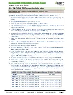
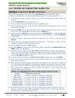
NATURAL GAS Combustion Calibration Instructions
15.
On Benchmark 3000 units
only
, once the manifold gas pressure is within the range in
table 4-1, record this value; it will be used later, in Section 5.2.2:
Low Pressure Gas Test
,
and Section 5.3.2:
High Pressure Gas Test
.
16.
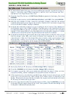
Press the Down▼ arrow key until
SET Valve Position
appears on the display, then press
CHANGE
.
17.
Press the Up
▲ arrow key until the
SET Valve Position
reads
100%
, then press
ENTER
.
18.
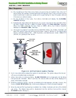
With the valve position at 100%, insert the combustion analyzer probe into the exhaust
manifold probe opening (see Figure 4-2a or 4-2b in Section 4.2.3) and allow enough time
for the combustion analyzer reading to stabilize.
19.
Compare the
combustion analyzer’s oxygen readings to the O
2
Sensor value displayed in
the
Operating
menu on the C-More Controller. The offset value in the
Calibration
menu can
be adjusted by
±3%
to make the on-board O
2
sensor match the value from the combustion
analyzer. If the values differ by more than
±3%
and your combustion analyzer is correctly
calibrated, the on-board O
2
sensor may be defective and need to be replaced.
20.
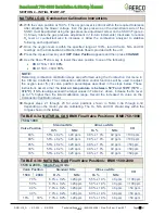
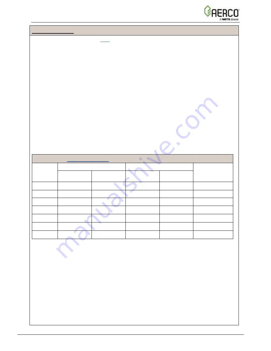
Compare the measured oxygen level to the oxygen range shown in Table 4-2. Also, ensure
that the nitrogen oxide (NO
x
) and carbon monoxide (CO) readings do not exceed the
values shown in Table 4-2. If your target NO
x
value is 9 ppm or less, use the values in the
Ultra-Low NO
x
columns. If you are not
in a “NO
x
-
limited” area and/or do not have a NO
x
measurement in your analyzer, set the oxygen (O
2
) at
5.5% ± 0.5%
.
TABLE 4-2: NATURAL GAS Calibration Readings 100% Valve Position
Model
Standard NO
x
Ultra-Low NO
x
Carbon
Monoxide (CO)
Oxygen (O
2
)
%
Nitrogen
Oxide (NO
x
)
Oxygen (O
2
)
%
Nitrogen
Oxide (NO
x
)
750
5.5% ± 0.2%
≤20 ppm
6.0% ± 1.0%
≤9 ppm
<100 ppm
1000
5.5% ± 0.2%
≤20 ppm
6.0% ± 1.0%
≤9 ppm
<100 ppm
1500
5.2% ± 0.2%
≤20 ppm
5.7% ± 1.0%
≤9 ppm
<100 ppm
2000
6.0% ± 0.2%
≤20 ppm
6.0% ± 1.0%
≤9 ppm
<100 ppm
2500
5.6% ± 0.2%
≤20 ppm
-
-
<100 ppm
3000
5.1% ± 0.2%
≤20 ppm
-
-
<100 ppm
3000 DF
5.3% ± 0.2%
≤20 ppm
-
-
<100 ppm
21.
Next, press the Down ▼ arrow key until
CAL Voltage 100%
is displayed.
22.
Press the
CHANGE
key and observe that
CAL Voltage 100%
is flashing.
23.
The oxygen level at the 100% valve position should match the value in Table 4-2. Also,
ensure that the NO
x
and CO readings do not exceed the values in Table 4-2.
24.
If the oxygen level is not within
the specified range, adjust the level using the ▲ and ▼
arrow keys. This will adjust the output voltage to the blower motor as indicated on the
display. Pressing the Up
▲ arrow key increases the oxygen level and pressing the down
▼ arrow key decreases the oxygen level.
25.
Once the oxygen level is within the specified range at 100%, press the
ENTER
key to store
the selected blower output voltage for the 100% valve position. Record all readings on the
Combustion Calibration Sheets provided.

