


Benchmark 750-3000 Installation & Startup Manual
SECTION 6
– BOILER SEQUENCING TECHNOLOGY
OMM-115_D
•
GF-200
•
5/9/2019
Technical Support
•
(800) 526-0288
•
Mon-Fri, 8 am - 5 pm EST Page 103 of
126
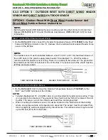
6.3.3 OPTION 3 - OUTDOOR RESET WITH DIRECT WIRED HEADER
SENSOR AND DIRECT WIRED OUTDOOR SENSOR
OPTION 3 - Outdoor Reset With Direct Wired Header Sensor And
Direct Wired Outdoor Sensor Instructions
NOTE:
Both Header Sensor AND Outdoor Sensor must be wired. See the
C-More Controller User
Manual
, OMM-0032 (GF-112) and
ProtoNode User Manual
, OMM-0080 (GF-129) for more
information.
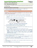
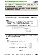
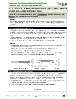
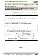
Step 1 - Direct Wired Header Sensor Wiring
1. On the MANAGER Unit, connect the Header Temperature Sensor (P/N
61040
) to the Feed
Forward (FFWD) terminals on the P-1 Harness Via the terminal block labeled
Header Temp
sensor
in the I/O Box.
NOTE:
The header sensor must be installed between 2 and 10 (0.61 and 3.1m) feet downstream of
the LAST boiler in the plant’s supply water header. Shielded pair 18 - 22 AWG cable is
recommended for header sensor wiring. There is no polarity to be observed. The ground for
the shield is at the “SHLD” terminal in the I/O the Box. The sensor end of the shield must be
left free and ungrounded.
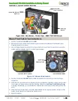
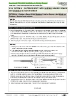
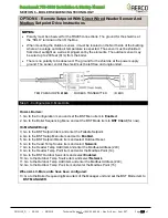
Step 2 - Direct Wired Outdoor Sensor
1. On the MANAGER Unit, Connect the Outdoor Temperature Sensor (P/N
61047
) to the
“OUT” and “COM” terminals in the I/O Box.
NOTES:
•
Twisted shielded pair 18 - 22 AWG cable is recommended for header sensor wiring. There
is no polarity to be observed. The ground for the
shield is at the “SHLD” terminal in the I/O
the Box. The sensor end of the shield must be left free and ungrounded.
•
When mounting the Outdoor sensor, it must be located on the North side of the building
where an average outside air temperature is expected. The sensor must be shielded from
direct sunlight as well as impingement by the elements. The outdoor sensor may be wired
up to 200 feet (61m) from the boiler.
TEMP SENSOR P/N
61047
I/O BOX
TEMP SENSOR P/N
61040
HEADER TEMP SENSOR I/O BOX


