User Guide
37
Setting up a routed network
• The Trusted interface ARP address replaces the router’s ARP address.
• All three Firebox interfaces are assigned the same IP address. This is true
whether or not you use the Optional interface.
• The majority of a LAN resides on the Trusted interface.
• You can have other networks in other address ranges behind the Firebox using
secondary networks. List the IP address of secondary networks in the
configuration file.
Use the sample network configuration and the Network Configuration Worksheet
(found in the
Install Guide
) to design your drop-in network. Then either run the
QuickSetup wizard to create a new configuration file or manually modify an existing
configuration file using Policy Manager. To set up a drop-in network, from Policy
Manager:
1
Select
Network => Configuration
. Click the
Drop-In Configuration
tab.
2
Enable the
Automatic
checkbox if you want the Firebox to use proxy ARP for all
hosts. Disable the checkbox if you want the Firebox to use proxy ARP only on
behalf of all hists on the network you specify with the
Default Network
drop-
down menu.
When automatic mode is enabled, the Hosts list is useful to lock a host to the specified interface.
To add specific hosts that the Firebox should use proxy ARP for, enter the IP address and the
interface they reside on in the Hosts section of the Drop-In Configuration tab.
3
Click
Add
to add a new host. To remove a host, select it and click
Remove
.
4
When you are done setting up your network, click
OK
.
Setting up a routed network
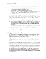
Use a routed network configuration when the Firebox is put in place with separate
logical networks on its interfaces. This configuration assigns separate network
addresses to at least two of the three Firebox interfaces.
If you have two separate network addresses and you want to use the routed
configuration, use only the External and Trusted interfaces (not the Optional
interface). Each interface must be on a separate network in routed configuration
mode.
If you have three or more network addresses, use the routed network configuration
and map a network to each interface. Add more networks as secondary networks to
one of the interfaces. You can relate different networks to different interfaces. Those
networks then come under the protection and access rules set up for that interface.
The Firebox forwards packets to the various interfaces depending on how you define
and configure services in Policy Manager.
Use the sample network configuration and the Network Configuration Worksheet
(found in the
Install Guide
) to design your routed network. Then either run the
QuickSetup wizard to create a new configuration file or manually modify an existing
configuration file.
Summary of Contents for Firebox FireboxTM System 4.6
Page 1: ...WatchGuard Firebox System User Guide Firebox System 4 6 ...
Page 16: ...6 ...
Page 20: ...LiveSecurity broadcasts 10 ...
Page 44: ...LiveSecurity Event Processor 34 ...
Page 52: ...Defining a Firebox as a DHCP server 42 ...
Page 68: ...Service precedence 58 ...
Page 78: ...Configuring a service for incoming static NAT 68 ...
Page 92: ...Establishing an OOB connection 82 ...
Page 94: ...84 ...
Page 112: ...HostWatch 102 ...
Page 118: ...Working with log files 108 ...
Page 130: ...120 ...
Page 158: ...Configuring debugging options 148 ...


