

FoldSmart™ Installation and Maintenance Manual
Revision 1 - MAY 2023
115
PHOTO EYE INSTALLATION TIPS
•
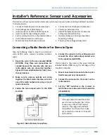
For pedestrian detection, mount thru-beam type photo eyes approximately 15" to 30" (.38 to .76m)
above the ground and as close to the gate as possible. A minimum of one photo eye is required, but
two is recommended, one photo eye to guard the open direction and the other for the close direction
of travel, unless gate edges for entrapment protection are installed.
•
Four wires to the receiver and two wires to the emitter are all that is required.
•
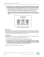
Depending on how the photo eyes are to be wired, +24VDC or +12VDC, power is provided via spades
located just to the right of the COM terminal strip near the left side of the board.
•
The receiver and emitter common wires are connected to the SENSOR COM terminal at the bottom,
left of the SmartDC Controller.
•
The photo eye NC output wires connect to the SmartDC Controller at the Appropriate Sensor Input (1,
2, or 3).
•
If tripped while in motion, the standard function is to stop the gate and automatically restart again if
the photo eye is clear within five seconds. An optional setting in the Installer Menu will cause a two
second reversal of travel, or, if closing, can be programmed to reverse to full open.
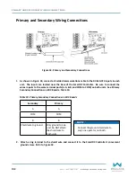
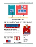
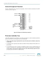
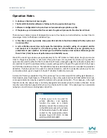
Sensor Common & +24V is the
recommended way to connect
monitored photo eyes to SmartDC
Controller.
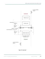
If photo eyes are to be used for
vehicle detection and logically
function the same as a vehicle
detector, connect the common wires
to the COM terminals on the left side
of the board and wire the NO output
contact to the appropriate vehicle
detector input: EXIT LOOP, IN OBS
LOOP, and OUT OBS LOOP.
If the photo eye has an internal switch for setting Light Operate vs. Dark Operate, select Light Operate.
If the photo eye has a relay output and has both NO and NC terminals, some experimentation may be
required to determine the proper connection. This is because, in the Light Operate mode, the output relay
is normally energized and releases when the beam is blocked. Some manufacturers label an output as
NO, when it is actually a NC contact. If the photo eye has a solid-state output you must choose a sinking
type connection.
Summary of Contents for FOLDSMART
Page 36: ...36 wallaceperimetersecurity com Phone 866 300 1110 FOLDSMART GATE INSTALLATION ...
Page 38: ...38 wallaceperimetersecurity com Phone 866 300 1110 FOLDSMART GATE INSTALLATION ...
Page 146: ......
Page 147: ...FoldSmart XT Drawings Generic Site Layout and Options ...
Page 148: ......
Page 149: ......
Page 150: ......
Page 151: ......
Page 152: ......
Page 153: ......
Page 154: ......
Page 155: ......
Page 156: ......
Page 157: ......
Page 158: ......
Page 160: ......


