background image

38

GM 5000EA

OPERATING MANUAL

EDITION 04/2016

ORDER NUMBER DOC2344499

6.5.5 

GROUNDING

Perfect grounding of all conductive parts such  as fl oors, walls, roofs is important for 
optimum coating and safety. Barriers, work pieces, transport devices, coating product 
tank, coating product supply or construction parts in the spray area with exception of the 
high-voltage parts during normal operation.
Parts of the booth must be grounded in accordance with EN 12215.

Discharge of electrostatically charged components in 
atmospheres containing solvents!

Explosion hazard from electrostatic sparks or fl ames.

  Ground all device components.
  Ground the work pieces to be coated.

WARNING

Heavy paint mist if grounding is insuffi

  cient!

Danger of poisoning.
Insuffi

  cient paint application quality.

  Ground all device components.
  Ground the work pieces to be coated.

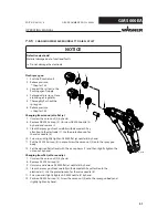
WARNING

A poorly grounded work piece causes:

- very bad wrap around,
- uneven coating,
- back spraying to the spray gun (contamination) and coater.

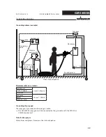
Prerequisites for perfect grounding and coating are:

- Clean work piece suspension.
- Grounding of spray booth, conveyor system and suspension on the building side in 

accordance with the operating manuals or the manufacturer's information.

- Grounding of all conductive parts within the working area.
- The grounding resistance of the work piece may not exceed 1 MΩ (megohm). 

(Ground leakage resistance measured at 500 V or 1000 V)

- Connect the control unit to the signal ground.
- Connect all ground cables using a short and direct route.
- Safety shoes and gloves, if used, must be static dissipative.

Summary of Contents for GM 5000EA

Page 1: ...B_03229 C us Electrostatic Air Spray Gun for manual operation for flat or round jet nozzles Version 04 2016 Translation of the Original Operating Manual...

Page 2: ......

Page 3: ...Work Environment 15 4 2 Safety Instructions for Staff 16 4 2 1 Safe Handling of WAGNER Spray Devices 16 4 2 2 Grounding the Device 17 4 2 3 Product Hoses 17 4 2 4 Cleaning and Flushing 18 4 2 5 Handl...

Page 4: ...sioning 41 6 7 3 1 Gun Cables and Gun Cable Extensions 42 6 7 4 Verifying a Safe Operational Condition 43 7 OPERATION 44 7 1 Training the Operating Staff 44 7 2 Safety Instructions 44 7 2 1 Emergency...

Page 5: ...3 Nozzle set EARV 77 13 4 Flat Jet Nozzles 77 13 4 1 AF 5000 Air Caps 77 13 4 2 AF 5000 Nozzles 78 13 5 Hoses and Electric Cables 79 13 5 1 Standard Hose Sets and Components 79 13 5 2 Hose Sets for L...

Page 6: ...6 GM 5000EA OPERATING MANUAL EDITION 04 2016 ORDER NUMBER DOC2344499 Table of Contents 15 2 Warranty Claim 101 15 3 FM Approval 102...

Page 7: ...onsequences of not observing the warning instructions The signal word indicates the hazard level The measures for preventing the hazard and its consequences WARNING This notice warns you of a hazard P...

Page 8: ...lists Electrostatics Air Manual gun Low R Low resistance Polyether ether ketone high temperature resistant thermoplastic plastic Stainless steel Position Number of pieces Wrench size The GM 5000EA op...

Page 9: ...er behavior as well as the necessary protective devices and measures Electrician Can assess the work assigned to him her and detect possible hazards based on his her technical training knowledge and e...

Page 10: ...d in potentially explosive areas see explosion protection marking in Chapter 3 WAGNER accepts no liability for any damage arising from incorrect use Use the device only to work with the products recom...

Page 11: ...ailable on the market that do not directly measure the specific paint resistance Multiplying the result of the measurement with the device specific cell constant K we obtain the specific resistance va...

Page 12: ...orking area Lacquering outside the defined working area Inhalation of substances hazardous to health Observe work and operation instructions Operation maintenance The forms of misuse listed below may...

Page 13: ...aximum surface temperature 85 C 185 F Maximum permissible product temperature 50 C 122 F Permissible ambient temperature 0 to 40 C 32 to 104 F For electrostatic finishing applications using class I gr...

Page 14: ...Temp code T6 1 3 4 5 6 7 2 8 9 10 B_03558 S OPERATING MANUAL EDITION 04 2016 ORDER NUMBER DOC2344499 3 2 TYPE PLATE Serial number The serial number S on the underside of the handle 1 Warning Danger of...

Page 15: ...ith EN 1149 5 The measured insulation resistance must not exceed 100 megohms Paint mist extraction systems ventilation systems must be fitted on site according to local regulations Ensure that the fol...

Page 16: ...devices DGUV regulation 100 500 For shut down devices the examination can be suspended until the next start up Carry out the work steps as described in the Pressure Relief chapter If pressure relief i...

Page 17: ...ion hoses may not be subjected to pressure Several liquids have a high expansion coefficient In some cases their volume can rise with consequent damage to pipes fittings etc and cause fluid leakage Wh...

Page 18: ...may be used for cleaning and flushing agents The tanks must be grounded An explosive gas air mixture forms in closed tanks Never spray into a closed tank when using solvents for flushing External clea...

Page 19: ...turer of the lacquers solvents and cleaning agents being used Take the specified protective measures in particular wear safety goggles protective clothing and gloves as well as skin protection cream i...

Page 20: ...ice may form electrostatic charges Flames or sparks can form during discharge Remove deposits from the surfaces to maintain conductivity Use only a damp cloth to clean the device Safe handling of WAGN...

Page 21: ...Cover 10 Handle Description 11 Adjusting screw stop 12 Trigger lever 14 Nozzle AR 5000 accessories see Chapter 13 15 Sealing plug 16 Air regulation 17 Electric cable connection 18 Atomizing air connec...

Page 22: ...the gun display 2 as follows Recipe 1 Recipe 2 Recipe 3 Recipe change R1 R2 R3 R1 Press the operating button 4 and hold the button pressed for at least 2 seconds to go forward 1 recipe During spraying...

Page 23: ...an be used to activate one after the other the various functions of the spray gun An increase in the force needed to pull the trigger back will be perceived at the position where the product valve ope...

Page 24: ...FM approval in submission Each spray gun includes the following as standard equipment Order No Description 2309368 Valve needle assembly tool 2325263 Clamping screw assembly tool 2319653 Protection g...

Page 25: ...016 ORDER NUMBER DOC2344499 5 3 1 DESIGN VARIANTS Basic version GM 5000EA USA Order No 2344471 GM 5000EA 4 finger trigger USA Order No 2367744 Spiral hose GM 5000EA USA no FM approval in submission Or...

Page 26: ...erature 0 C 40 C 32 F 104 F Maximum permissible product temperature 50 C 122 F Maximum surface temperature 85 C 185 F Compressed air quality free from oil and water Quality standard 6 5 2 according to...

Page 27: ...230 C A B C A B B_03231 OPERATING MANUAL EDITION 04 2016 ORDER NUMBER DOC2344499 with flat jet nozzle mm inch A 261 10 28 B 46 1 81 C 245 9 65 Dimensions with round jet nozzle mm inch A 261 10 28 B 46...

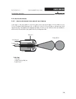
Page 28: ...ss the spray product is fed to the nozzle with a pressure of approx 0 05 0 2 MPa 0 5 2 bar 7 29 psi The atomizing air at approx 0 25 0 4 MPa 0 25 4 bar 36 58 psi produces a soft round jet which largel...

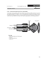
Page 29: ...rfect finish Spray product Spray angle In this process the spray product is fed to the nozzle at a pressure of 0 05 0 2 MPa 0 5 2 bar 7 29 psi The atomizing air at approx 0 25 0 4 MPa 2 5 4 bar 36 58...

Page 30: ...c field by means of the high voltage electrode As a result the paint particles atomized by the spray gun are carried to the grounded work piece by kinetic and electrostatic energy where they adhere fi...

Page 31: ...sizes Flow rate Electrostatics or or off 5 6 1 PRESSURE SETTINGS FOR ROUND JET NOZZLES Air regulation closed Air regulation opened There are 4 nozzle sizes D8 D12 EARV LV and EARV HV available The ai...

Page 32: ...n is reduced with this setting There are 8 flat jet nozzle sizes from 0 6 up to 2 0 available There are 2 air cap types s small w wide with 3 different nozzle sizes each Each air cap can be used in co...

Page 33: ...geneous distribution of paint particles on the object See also Chapter 5 5 3 5 6 5 DISCHARGE QUANTITY MEASUREMENTS Product pressure in bar Discharge quantities in g min Flat spray nozzles Device GM 50...

Page 34: ...the device must be stored in a dry location free from vibrations and with a minimum of dust The device must be stored in closed rooms The air temperature at the storage location must be between 20 C a...

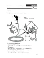
Page 35: ...unit 10 Product hose 11 Compressed air main 12 GM 5000EA R spray gun 13 Tank for return flow 14 Protective hose 15 Mains cable Example Electrostatic air spraying system with pressure tank 6 5 1 TYPICA...

Page 36: ...l and safety regulations for the additionally required system components WARNING Toxic and or flammable vapor mixtures Risk of poisoning and burns Operate the device in a spray booth approved for the...

Page 37: ...t supply with a suitable flushing agent NOTICE Bursting hose bursting threaded joints Danger to life from injection of product Ensure that the hose material is chemically resistant to the sprayed prod...

Page 38: ...nt mist if grounding is insufficient Danger of poisoning Insufficient paint application quality Ground all device components Ground the work pieces to be coated WARNING A poorly grounded work piece ca...

Page 39: ...urn flow Grounding scheme example Conveyor Mains cable Minimum cable cross section Control unit Product supply Paint tank Conveyor 16 mm2 AWG 6 Booth Spraying stand Grounding of spray gun The spray gu...

Page 40: ...37 100 100 1 30 34 41 120 120 1 2 33 41 49 140 140 1 4 37 45 58 160 160 1 6 43 50 66 180 180 1 8 46 54 74 200 200 2 49 58 82 220 220 2 2 52 62 240 240 2 4 56 65 260 260 2 6 62 68 280 280 2 8 65 70 300...

Page 41: ...ontrol unit See Chapter 6 7 3 1 Visually check the permissible pressures for all the system components When using a WAGNER pneumatic pump Check the level of the separating agent and fill the separatin...

Page 42: ...ected or connected in this area WARNING 6 7 3 1 GUN CABLES AND GUN CABLE EXTENSIONS The following points must be noted The cable connection to the gun and the connection to a cable extension may not b...

Page 43: ...SAFE OPERATIONAL CONDITION Attention guns with electric extension cable Secure the cover sleeves with the warning sign by means of the screws 84 on the connectors Power loss In order to prevent power...

Page 44: ...100 megohms WARNING Observe safety instructions in Chapter 4 Incorrect operation Risk of injury and damage to the device The operating staff must be qualified to operate the entire system The operatin...

Page 45: ...or solvent Never reach into the spray jet Never point the spray gun at people Consult a doctor immediately in the event of skin injuries caused by paint or solvent Inform the doctor about the paint o...

Page 46: ...i on the pressure regulator 3 5 Point the gun without nozzle into tank 13 and open it 6 Close stop valve 2 as soon as pure working material without any air inclusions starts coming from the gun 7 Clos...

Page 47: ...ation is achieved 7 Adjust the atomizing air regulator 4 until optimal atomization is achieved 8 Flat jet process with the air adjustment on the gun set the ratio of shaping air atomizing air so as to...

Page 48: ...pply on 7 Adjust the product pressure and atomizing air in accordance with the nozzle and object Rule of thumb Set atomizing air pressure approx three times higher than the product pressure Flat jet m...

Page 49: ...illustration shows the influence of the turning on the spraying pattern 1 Set the union nut as far as the stop 2 Open maximum 1 4 turn The atomizing is good in this area The union nut should not prot...

Page 50: ...is maintained Cleaning tasks are carried out on the spraying system The spraying system is moved to another location Something must be checked on the spraying system The nozzle is removed from the gu...

Page 51: ...lean the spray gun front carefully with damp cloth Pay attention to the electrode 1 Use the protection cap for the valve needle 8 10 Screw in and slightly tighten AF 5000 flat jet nozzle 6 by hand 11...

Page 52: ...en the valve housing 7 3 6 CLEANING OF THE NOZZLE PARTS The nozzle parts 2 3 4 5 and 6 may only be immersed into a cleaning solvent recommended by the lacquer manufacturer and must be removed again im...

Page 53: ...TRUCTIONS 8 1 1 CLEANING STAFF Observe safety instructions in Chapter 4 DANGER Incorrect maintenance repair Danger to life and equipment damage Only a WAGNER service center or a suitably trained perso...

Page 54: ...to be cleaned and which product has to be removed When cleaning the spray gun only use non polar cleaning agents to prevent conductive residues on the surface of the spray gun Should it however be nec...

Page 55: ...ses Examine the compatibility of the cleaning and flushing agents and working media on the basis of the safety data sheets WARNING Damage to electrical devices Never immerse the spray gun in cleaning...

Page 56: ...sure generator 6 Point the spray gun toward the collecting tray and actuate the trigger Flush the gun thoroughly as soon as clean flushing agent emerges 7 Remove flushing agent supply Blowing out the...

Page 57: ...that the device is checked for being in a reliable state after maintenance work is completed 8 2 1 MAINTENANCE STAFF 8 2 2 SAFETY INSTRUCTIONS Observe the safety instructions in Chapter 4 and Chapter...

Page 58: ...ing and service manual for all work For the safe operation of electrostatic manual coating systems for flammable liquid coating products intervals for periodical inspections are defined as follows Ins...

Page 59: ...tal influences even when handled correctly Check hoses pipes and couplings every day and replace if necessary Before every commissioning check all connections for leaks Additionally the operator must...

Page 60: ...r grounding at object Check grounding of object or hanger with ohmmeter Lacquer resistance too high too low Check lacquer resistance see Chapter 2 5 Spraying pressure too high Readjust spraying pressu...

Page 61: ...ion Chapter 6 7 and check for leaks Chapter 11 3 Function test in accordance with Chapter 11 In accordance with the guideline for liquid ejection devices DGUV regulation 100 500 The liquid ejection de...

Page 62: ...e 11 Wrench size 12 Wrench size 14 Wrench size 19 Ring spanner SW9 Ring spanner SW11 Torx wrench 20 Torx wrench 25 Slide gauge Valve needle assembly tool Order No 2309368 Clamping screw assembly tool...

Page 63: ...SW19 Torx 25 1 2 3 B_03246 SW3 SW12 SW12 OPERATING MANUAL EDITION 04 2016 ORDER NUMBER DOC2344499 10 3 2 DISMANTLING OF THE SPRAY GUN Air hose When unscrewing the air hose a second open ended box wre...

Page 64: ...emove it Air distribution 9 1 Locate the start of the thread for recessed internal threading 2 Lever under the air distribution ring directly in front of the start of the thread using screwdriver no 1...

Page 65: ...required Remove rod seal 10 Do not damage the housing in the process Two gold contact sleeves either remain in the handle 1 or are seated on the two gold pins 2 Do not lose 1 Loosen the oval head scr...

Page 66: ...smantled parts must be clean and dry after cleaning Care should be taken that these parts remain free of solvents grease or sweat from the hands salt water Clean and mount wearing gloves Spare parts m...

Page 67: ...sparingly Ensure the correct insertion position Ensure the correct insertion position Only as required if the seal was removed press in using handle seal assembly tool Order No 2342334 not included i...

Page 68: ...acking 9 grease slide together screw together 10 Grease clamping screw 1 and mount using assembly tool 5 Insert spring 4 Coat the hollow section with a brush Note avoid the pin and hexagon sparingly V...

Page 69: ...he rear position so that the sealing area does not become scratched 1 2 Very slightly tighten valve tip 2 using an assembly tool with three fingers 3 Use socket or ring spanner no wrench to tighten th...

Page 70: ...ack in cover 5 e g press on table In the process only exert counter pressure on the sleeve bracket and not on the entire cover 2 Position cover straight and level and carefully press in Use only minim...

Page 71: ...ITION 04 2016 ORDER NUMBER DOC2344499 Flat jet nozzle Diverse nozzle sizes see Chapter 13 4 Round jet nozzle Diverse nozzle sizes see Chapter 13 3 Air hose When screwing on the air hose a second open...

Page 72: ...be checked with the display on the control unit VM 5000 Note The gun must be clean and dry and must not have any paint or cleaning agent residues In the case of ambient air with a high air humidity th...

Page 73: ...N 04 2016 ORDER NUMBER DOC2344499 Disruptive discharge test Check the gun against ground with the grounding rod No sparks should be formed Note in the vicinity of the electrode harmless corona dischar...

Page 74: ...rigger test for air seal at the points marked in the illustration Connect low pressure hose to the spray gun Spray gun with suitable medium e g flushing agent or Marcol 52 and a maximum pressure of 0...

Page 75: ...of with the household refuse but must be recycled in an environmentally correct manner WAGNER or one of our dealers will take back your used WAGNER electric or electronic equipment and will dispose of...

Page 76: ...o Designation 2312184 Valve tip Air complete PEEK standard version 2312185 Valve tip Air complete steel 13 1 VALVE HOUSING 13 2 VALVE TIPS B_03238 B_03238 B_03239 B_03239 13 3 2 AR 5000 NOZZLES Order...

Page 77: ...14255 Air cap AF 5000 0 4 0 8W wide 2314256 Air cap AF 5000 1 0 1 4W wide 2314258 Air cap AF 5000 1 6 2 0W wide 13 4 FLAT JET NOZZLES 13 4 1 AF 5000 AIR CAPS 13 3 3 NOZZLE SET EARV Order No Designatio...

Page 78: ...10539 Nozzle AF 5000 0 6 mm black 2310540 Nozzle AF 5000 0 8 mm yellow 2310541 Nozzle AF 5000 1 0 mm red 2310542 Nozzle AF 5000 1 2 mm green 2310543 Nozzle AF 5000 1 4 mm brown 2310544 Nozzle AF 5000...

Page 79: ...Low pressure hose DN6 PN20 NPSM 3 8 10 m PA 3 1 2356979 Air hose complete DN8 USA 10 5 m 4 1 2339158 Gun cable GM 5000E 15 0 m 5 10 5 m 3676437 Protection hose fabric PP30 10 5 m Order No Designation...

Page 80: ...e set GM 5000EA USA 7 5 m 29 2 47 2 300 10 20 10 1500 100 2356992 Hose set GM 5000EA USA 10 m 29 2 47 2 300 10 20 10 1500 100 2356993 Hose set GM 5000EA USA 15 m 29 2 47 2 300 10 20 10 1500 100 235699...

Page 81: ...1 9971025 O ring Order No Designation 1 1 2357022 Hose set GM 5000EA USA 10 0 m Low R Consists of 2 1 2310465 Product hose EA complete 10 0 m Low R 3 1 2345341 Air hose complete 10 5 m 4 1 2339158 Gun...

Page 82: ...signation 1 1 2357024 Hose set GM 5000EA USA 20 0 m Low R Consists of 2 1 2310467 Product hose EA complete 20 0 m Low R 3 1 2345343 Air hose complete 20 5 m 4 1 2339160 Gun cable GM 5000E 25 0 m 5 20...

Page 83: ...182 1 2357023 Hose set GM 5000EA 15 m Low R 200 2 171 2 300 10 20 10 1500 100 182 1 2357024 Hose set GM 5000EA 20 m Low R 200 2 171 2 300 10 20 10 1500 100 182 1 Notes Melt the hose ends at both sides...

Page 84: ...er 6 7 3 1 Length 10 m 32 8 ft 20 m 65 6 ft Order No 2339161 2339162 13 5 5 AIR REGULATION Order No Designation 2357053 Air regulation PB complete 13 5 3 SPIRAL HOSE NO FM APPROVAL Order No Designatio...

Page 85: ...MANUAL EDITION 04 2016 ORDER NUMBER DOC2344499 13 5 6 4 FINGER TRIGGER Order No Designation 2367641 4 finger trigger Order No Designation 2367508 Hose holder 4 finger trigger open Order No Designatio...

Page 86: ...99 Order No Designation 2319653 Protective gun coating 259010 High voltage tester HV 200 N 2326041 Paint resistance meter 999080 Wet film thickness gauge 50342 Viscosity cup DIN 4 mm 0 16 inch 2309368...

Page 87: ...al mail express delivery air freight courier etc Identification in spare parts lists Explanation of column labeling in the following spare parts lists Wearing parts Note These parts are not covered by...

Page 88: ..._03235 2 20 21 19 7 5 8 9 10 22 12 11 13 14 15 18 16 17 6 1 OPERATING MANUAL EDITION 04 2016 ORDER NUMBER DOC2344499 14 2 GM 5000EA SPRAY GUN Dismantling and assembling see Chapter 10 14 2 1 BASIC VER...

Page 89: ...gon socket cylinder head screw 9 1 2312183 Lid complete including item 22 10 1 9900386 Hexagon socket cylinder head screw 11 1 2311970 Sealing plug 12 1 2307104 Screw plug 13 1 2312180 Air regulation...

Page 90: ...GM 5000EA B_06066 2 20 21 19 7 5 8 9 10 22 12 11 13 14 15 18 16 17 6 1 OPERATING MANUAL EDITION 04 2016 ORDER NUMBER DOC2344499 14 2 2 SPIRAL HOSE FOR GM 5000EA Dismantling and assembling see Chapter...

Page 91: ...cylinder head screw 9 1 2312183 Lid complete including item 22 10 1 9900386 Hexagon socket cylinder head screw 11 1 2311970 Sealing plug 12 1 2307104 Screw plug 13 1 2312180 Air regulation complete in...

Page 92: ...5000EA B_06065 2 20 21 19 7 5 8 9 10 22 12 11 13 14 15 18 16 17 6 1 OPERATING MANUAL EDITION 04 2016 ORDER NUMBER DOC2344499 14 2 3 4 FINGER TRIGGER FOR GM 5000EA Dismantling and assembling see Chapt...

Page 93: ...n socket cylinder head screw 9 1 2312183 Lid complete including item 22 10 1 9900386 Hexagon socket cylinder head screw 11 1 2311970 Sealing plug 12 1 2307104 Screw plug 13 1 2312180 Air regulation co...

Page 94: ...94 GM 5000EA B_04367 2 1 12 10 9 8 3 4 24 5 6 7 21 22 11 25 OPERATING MANUAL EDITION 04 2016 ORDER NUMBER DOC2344499 14 2 4 GM 5000EA ADAPTER Dismantling and assembling see Chapter 10...

Page 95: ...312185 Valve tip Air complete steel 6 1 2314271 Adapter GM 5000EA 7 1 2312181 Cascade complete 8 1 9974166 O ring 9 1 2307062 Clamping screw valve rod 10 1 2311562 Rod seal 11 1 2312177 Valve rod unit...

Page 96: ...96 GM 5000EA B_06067 7 8 9 12 6 3 2 1 4 24 25 10 18 13 5 23 26 4 4 OPERATING MANUAL EDITION 04 2016 ORDER NUMBER DOC2344499 14 2 5 GM 5000EA HANDLE Dismantling and assembling see Chapter 10...

Page 97: ...ug complete including item 23 6 1 2314270 Handle complete 7 1 2307232 Adapter seal 8 1 2325789 Adjusting screw complete 9 1 2309825 Oval head screw with hexagon socket 10 1 2310692 Seal 12 1 2307281 T...

Page 98: ...SPARE PARTS LISTS Notes concerning AR5000 D8 nd D12 nozzles Parts 3 and 4 can be pushed out of the nozzle with a suitable pin 2 0 2 3 mm 0 08 0 09 inch NOTICE Incorrect assembly Damage to the parts or...

Page 99: ...ation 1 1 2315050 Nozzle AR 5000 complete D12 2 1 2327661 Nozzle AR D12 3 1 2327662 Nozzle attachment AR D12 4 1 2327663 Air diffuser AR D12 Wearing part 14 3 1 AR 5000 NOZZLE D8 AR 5000 nozzle D8 spa...

Page 100: ...ducts High viscosity HV products Designation Order No Order No 1 1 Nozzle set EARV 5000 2361290 2365979 2 1 Nozzle EARV 2361273 3 1 Nozzle insert EARV 2361274 4 1 Union nut EARV 2361272 2365978 5 1 O...

Page 101: ...ess of the purchaser We do not provide warranty for damage that has been caused or contributed to for the following reasons Unsuitable or improper use faulty assembly or commissioning by the purchaser...

Page 102: ...Applicators for use with VM 500 and VM 5000 Control units for use in Electrostatic Finishing Applications using Class I Group D Spray Materials when configured in accordance with drawing 2316160 The G...

Page 103: ......

Page 104: ...2344499 Edition 04 2016 Germany Phone Telefax E mail Switzerland Phone Telefax More contact addresses on the internet at Company Locations WAGNER worldwide Subject to changes without notice Document...

Reviews: