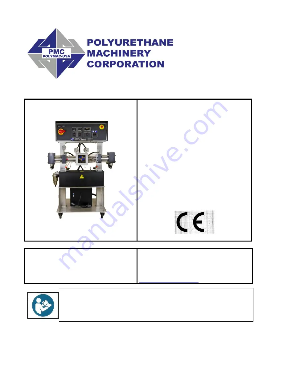
background image


PMCA-20 

Proportioner 

Manual 

Pneumatic, Heated, Plural Component 

Proportioner 

For spraying Polyurethane Foam and 

Coatings 

For Professional Use Only 

Not approved for use in 

Explosive atmosphere locations


    Ref. # MN-06001 


REVISION 1.0


Polyurethane Machinery Corp. 

Headquarters: 1 Komo Drive, Lakewood NJ 08701 

Manufacturing: 2 Komo Drive, Lakewood, NJ 08701 

Phone: 732-415-4400         Fax: 732-364-4025 

http://www.polymac-usa.com


Before  installing  the  PMCA-20  Series  Proportioner  and  start-up,  carefully  read  all  the 
technical  and  safety  documentation  included  in  this  manual.    Pay  special  attention  to  the 
information in order to know and understand the operation and the conditions of use of the 
PMCA-20 Series Proportioner.  All of the information is aimed at improving user safety and 
avoiding possible breakdowns from the incorrect use of the PMCA-20 Series Proportioner. 

Summary of Contents for MN-06001

Page 1: ...ive Lakewood NJ 08701 Phone 732 415 4400 Fax 732 364 4025 http www polymac usa com Before installing the PMCA 20 Series Proportioner and start up carefully read all the technical and safety documentation included in this manual Pay special attention to the information in order to know and understand the operation and the conditions of use of the PMCA 20 Series Proportioner All of the information i...

Page 2: ...RIPTION 11 INSTALLATION 14 Heated Hose Installation 15 PROPORTIONER PURGING 19 DIGITAL TEMPERATURE CONTROLLER 21 START UP 22 SHUT DOWN 23 TROUBLESHOOTING 24 Heaters 25 Hose Heat 28 Pneumatic Drive System 31 Metering Pump Line 33 MAINTENANCE 36 Inlet Material Screens 36 Iso Pump Lube System 37 Metering Pump Line 37 Pump Base Service 38 Material Heater 39 REPLACEMENT KITS 41 DOUBLE ACTING PROPORTION...

Page 3: ... Pump Assembly Size 60 40 48 R Pump Assembly Size 60 40 49 Piston Assembly Size 60 40 50 Pumpbase Assembly 51 Pre Heater Assembly 52 Y Strainer Assembly A R Side 54 Air Machine 55 Lube Bottle Components 60 Hoses 61 TECHNICAL SERVICE BULLETIN 63 MANUAL REVISIONS 66 ...

Page 4: ...ber The Warranty does not cover any Product if the Original Invoice appears to have been modified or altered or when the serial number on the Product appears to have been altered or defaced Product Maintenance It is the Customer s responsibility to maintain the Product properly See your maintenance schedule and owner s manual for details The Warranty does not cover an improperly maintained Product...

Page 5: ...oducts Repaired or Replaced under Warranty Following the repair or replacement of a Product covered by this Warranty such Product will continue to be subject to the original Warranty for the remainder of original Warranty Period or for three 3 months from the repair or replacement date whichever is longer No Rights Implied Nothing in the sale lease or rental of any Product by PMC shall be construe...

Page 6: ... of this manual will enable the operator to know the characteristics of the PMCA 20 Series Proportioner and the operating procedures By following the instructions and recommendations contained herein you will reduce the potential risk of accidents in the installation use or maintenance of the PMCA 20 Series Proportioner you will provide a better opportunity for incident free operation for a longer...

Page 7: ...imitation gloves protective goggles safety footwear and face masks Use breathing equipment when working with the PMCA 20 Series Proportioner in enclosed spaces or in areas with insufficient ventilation The introduction and follow up of safety measures must not be limited to those described in this manual Before starting up the PMCA 20 Series Proportioner a comprehensive analysis must be made of th...

Page 8: ...s includes but is not limited to the use of protective goggles gloves shoes and safety clothing and breathing equipment Utiliser une protection appropriée utilisation d entretien ou d être présents dans la région où le matériel fonctionne Cela inclut mais n est pas limité à l utilisation de lunettes de protection gants chaussures et vêtements de sécurité et un équipement respiratoire The equipment...

Page 9: ...ngth of 310 ft 93 m The system includes an innovative hose heating concept in which the continuous braid tinned copper jacket is distributed evenly around the circumference of the hose providing a uniform heating watt density and precise control of the material application temperature This hose heating element design is extremely resistant to fatigue failure 100 circumferential coverage produces t...

Page 10: ...eated Hoses MA 00039A and MA 00039A TC Maximum production ratio 1 1 60 pumps 18lb min 1 8 gals min 9kg min 7 2 lpm Maximum production ratio 1 1 40 pumps 12 lb min 1 2gals min 6kg min 2 4 lpm Minimum production 2 lb min 1kg min Maximum hose length 310 ft 93 m Dimensions 30in W x 26in D x 45in H NOTE The PMCA Series is designed to be used with a PMC Spray Gun 3500 PSI 241 Bar or equivalent that is r...

Page 11: ...PMCA 20 Manual 11 DESCRIPTION PMCA 20 ...

Page 12: ...m H Isocyanate Iso A Safety Pressure Switch Disables the pump circuit in the event of excessive pressure in the Isocyanate system I Heater Thermocouple Provides temperature information of the chemical to its Temperature Controller J Polyol Poly R Pressure Gauge Indicates the pressure in the Polyol system K Polyol Poly R Safety Pressure Switch Disables the pump circuit in the event of excessive pre...

Page 13: ...d the main machine display will illuminate Q Heater Controller Switch Turns ON and OFF power to the Heaters See detailed Temperature Controller instructions R Hose Heater Control Switch Automatically controls the Hose Heater only when using the TSU Temperature Sensing Unit probe S Cycle Counter Used to calculate the amount of chemical processed T Pump Switch Off Removes power from the pump circuit...

Page 14: ...ly must meet the specifications indicated on the Serial Number Placard affixed to the Electric Console CAUTION Make sure the power cable is disconnected from the main power source before connecting to the Terminal Strip in the Console Follow the recommended procedure in the indicated order to install the proportioner 1 Insert the main power cable by passing it through the strain relief at the bott...

Page 15: ...e sized open end wrench after ensuring Heated Hose assemblies lay flat CAUTION Take care to not cross thread or over tighten the Coupling Connections Thread sealant tape or compound is not required for this tapered seat Coupling Connections 2 Connect the material Heated Hoses to the outlets of the respective Heater connections i e Iso A Heated Hose to the Iso A Heater connection and the Poly R Hea...

Page 16: ...U be installed between the last section of Heated Hose and the Gun Whip Carefully straighten the sensing wire inserting it in the Iso A Heated Hose and tighten fluid fittings with appropriate sized open end wrenches CAUTION To protect the TSU sensor you must pay special attention not to kink or excessively bend the Heated Hoses Do not coil the Heated Hoses with a diameter of less than 4 feet CAUTI...

Page 17: ...g matches the Heated Hose length installed If Heated Hose sections are added or removed the Tap setting should be changed to a setting which will limit the maximum amperage in the Heated Hose to 52 amps The suggested settings are tabled below 6 Ensure the Manual Valves are CLOSED and connect the Coupling Block to the Heated Gun Whip CAUTION Excessive force closing or opening the Manual Valves may ...

Page 18: ...g errors in connection a Make sure that the Inlet Valves on the Proportioner are closed b Connect one end of the Polyol R Material Delivery Hose thread to the proportioner Polyol R Inlet Valve and the other end to the Polyol R Transfer Pump c Connect one end of the Iso A Material Delivery Hose thread to the proportioner Iso A Inlet Valve and the other end to the Iso A Transfer Pump d Connect the a...

Page 19: ...oner Inlet Valves are CLOSED c All connections are tight d Material should be stored to the material suppliers recommended temperatures 2 Slowly OPEN the Poly R Transfer Pump Air Shut Off Valve allowing Pump to cycle slowly as it fills the Material Delivery Hose to the Proportioner Check for leaks 3 OPEN Poly R Coupling Block Manual Valve over a waste container 4 Slowly OPEN Proportioner Poly R In...

Page 20: ... G J page 12 should read the same Check all Heated Hose Coupling connections for leakage 13 Check the TSU for leaks and that all Fast Lock connections are tight and electrical tape is installed over their set screws 14 Bundle all Heated Hose Connections ensuring no TSU Cable or Air Hose kinks Wrap with Electrical Tape to securely hold all components in place and minimize places for bundle to snag ...

Page 21: ...ton The display will flash and indicate its current set point 3 Press and hold the or to increase or decrease the material temperature set point to the desired value as determined by the material supplier or application conditions 4 Once the set point is entered the controller will go back to ambient temperature on its own 5 8 seconds WARNING The Controllers are factory programmed and are not fiel...

Page 22: ...void excessive pressure in the Proportioner wait for the Hose Heater to reach its set point temperature before continuing 8 Turn ON the Primary Heater and confirm material set point temperature as required by the material supplier or application conditions has been reached 9 Set Pump Switch to NORMAL One of the Directional Indicator Lights will light indicating Metering Pump direction and the Mete...

Page 23: ...he day 1 Set the Pump Switch to RETRACT 2 Spray off the application surface until Material Pressure Gauges readings begin to fall CAUTION To avoid possible Proportioning Pump Seal weepage and moisture vapor drive into the Heated Hoses the system pressure should not be reduced to zero It is recommended to lower the system pressure to a minimum of 400 psi 27 6 Bar 3 CLOSE the Spray Gun Coupling Bloc...

Page 24: ... Pour éviter les dommages causés par l impact des fluides sous pression ne pas ouvrir un lien ou d effectuer des travaux d entretien sur les éléments soumis à la pression jusqu à ce que la pression a été complètement éliminé Use suitable protection when operating maintaining or being present in the area where the equipment is functioning This includes but is not limited to the use of protective go...

Page 25: ...ct with the Heater body If the surface temperature exceeds 225 F 107 C the Limit Switch will shut off the Heater power The Limit Switch will not reset until the temperature in the Heater is below 190 F 88 C Follow the recommended procedure in the indicated order to solve the problem and avoid unnecessary repairs Make sure all Switches are in the correct position and Indicator Lights ON before dete...

Page 26: ... you have a 208 230 volt reading the relay has malfunctioned and needs to be replaced If the AC voltage reads zero remove the pre heater cover and look for loose or broken wires If there is no LED light on the solid state relay move to the next step 3 With a DC volt meter read across position A1 and A2 on the solid state relay smaller wires if you have a reading of 4 6 volts DC replace the solid s...

Page 27: ...ler Briefly turn on the heater and look for the LED light on the solid state relay to be on If the light is on replace the controller If the light is off replace the solid state relay PROBLEM Primary heater Temperature drops excessively while spraying SOLUTIONS 1 Temperature of the chemical in the containers is too cold 2 Exceeding the flow rate specification of the machine 3 Disconnect power to t...

Page 28: ...se circuit turned on measure across the two leads coming out of the transformer that are connected to the A and R hose If you are reading voltage your volt reading will vary depending on what tap setting is used most likely the problem is in the heated hose Either a connector has come loose or there is a broken wire Because the gun whip takes the most abuse it is most likely that the whip has fail...

Page 29: ...ONS 1 Check position 6 and 7 on the heater controller for loose wires If the wires are tight move to the next step 2 Remove the transformer cover and check that the thermocouple wires are secure to the harness going up to the controller If there are no loose connections disconnect the wire from the TSU and connect it directly to the thermocouple harness coming out of the hose transformer If the co...

Page 30: ...ove the tap setting higher up one CAUTION Do not exceed the value of the transformer hose breaker WARNING Before correcting any kind of defect make sure the Main Power Switch is OFF and incoming power is locked OFF NEVER access the inside of the Control Panel with the Proportioner power supply ON The Pneumatic Unit is a component that works under pressure Do not open any connection or carry out ma...

Page 31: ...HE ROLLER 2 Remove the reversing switch cover and the clear plastic cover that protects the R side pump shaft With an ohms meter take a continuity reading on the left switch facing the machine by touching the two screws that have the wires attached normally open there should be no continuity until the roller on the switch is depressed If this switch is good check the one on the right by touching t...

Page 32: ... has the higher reading This will drop the pressure on the high side and bring up the pressure on the low side when the pressures are within 200 psi 13 8 bar of each other close the manual valve The pump light will come back on if this was the problem and the pump circuit will be activated If the problem continues refer to the troubleshooting section of the metering pump line or the spray gun manu...

Page 33: ...sure indicated on one or both of the material Pressure Gauges is an indication of an over pressure condition The Safety Pressure Switches are a momentary design when the pressure bleeds off the Metering Pump Line will resume normal operation However the cause of the over pressure should be determined and corrected The three most common causes are a Cavitation of the Metering Pump on the low pressu...

Page 34: ...PMCA 20 Manual 34 MATERIAL CONDITION A GAUGE R GAUGE NORMAL LACK OF ISO A LACK OF POLY R RESTRICTION OF ISO A RESTRICTION OF POLY R ...

Page 35: ...ility d Inlet Material Screen obstructed See MAINTENANCE section e Metering Pump Inlet Ball does not seat properly allowing material to flow back into the Material Delivery Hose when the Metering Pump is on the Discharge stroke This causes the volume of material on that Metering Pump to be less on the discharge stroke resulting in intermittent off ratio material and Pressure Gauge fluctuation 4 Pr...

Page 36: ...bi weekly basis NOTE Inspect and clean Inlet Material Screens before Proportioner start up They should not be cleaned after the day s operation as the Proportioner should be purged immediately after inspection and cleaning This is to reduce the risk of moisture contamination contamination through the reaction with the solvent used in the cleaning operation and cross over at the Spray Gun due to ai...

Page 37: ...place the Reservoir in its support The system is auto suction and does not need priming when using size 60 pumps When using size 40 pumps priming may be necessary Metering Pump Line WARNING Before performing any maintenance make sure the Main Power Switch is OFF and incoming power is locked OFF Allow material temperature to cool below 80 F and bleed all material pressure to zero Weekly When the Pr...

Page 38: ...all d Using supplied Ball Seat Tool TL 02 check for proper Ball Seat Ball Seat Gasket compression Snug Seat up to turn maximum Pump Seal Replacement Refer to Parts Identification Drawings for reference NOTE When Iso A Proportioning Pump Cylinder is disassembled for service all parts included in the Seal Kit KT 05001 60 or KT 05001 40 should be replaced When the Poly R Proportioning Pump Cylinder i...

Page 39: ... Thermocouple is very important and must be done correctly before tightening the Nut 1 Unscrew the Nut that holds the defective Thermocouple and remove from the Body Disconnect Thermocouple wiring located under the Top Cover of the Heater Remove Body and discard 2 Install Connector Body into Heater using an open end wrench and tighten to prevent leakage Teflon Tape or appropriate Thread Sealant sh...

Page 40: ...le Body 2 Disconnect the suspect Heating Rod from the wire connections and test Heating Rod again for proper electrical resistance 1250 W Heating Rod is 39 0 ohms 3 Unscrew the Heating Rod and remove from the Heater Block along with its Spring and inspect it must be smooth and shiny in appearance If it is blackened or has material adhered to it replace the Heating Rod even if ohm reading is accept...

Page 41: ...0 PART NUMBER DESCRIPTION QTY OR 00011A O ring 2 OR 00046A O ring 2 PU 01002A B06 Cylinder Bearing 1 PU 01013A Flange Gasket 1 PU 01014A 006 Piston Support Washer 1 PU 01015A 006 Piston Seal Wiper 1 PU 01016A 006 Piston Seal 1 PU 01017A 006 Cylinder Seal 1 PU 05029 60 Pin 1 40 Iso A Pump Rebuild Kit KT 05001 40 PART NUMBER DESCRIPTION QTY OR 00011A O ring 2 OR 00020A O ring 2 OR 00044A O ring 1 OR...

Page 42: ...ump Line O ring Kit KT 05009 PART NUMBER DESCRIPTION QTY OR 00011A O ring 4 OR 00046A O ring 4 OR 00045A O ring 4 PU 01013A Gasket 2 OR 00044A O ring 1 OR 00020A O ring 2 PMC Recommended O ring Grease PART NUMBER DESCRIPTION QTY GP Lube Grease Lubriplate Grease 1 TL 04003 Grease Tube for use w Grease Gun 1 Heater Thermocouple Kit KT 05021 PART NUMBER DESCRIPTION QTY HI 05020 Body Nut Ferrule 1 HI ...

Page 43: ...PMCA 20 Manual 43 DOUBLE ACTING PROPORTIONING PUMP DIAGRAM FILL STROKE DISCHARGE STROKE ...

Page 44: ...PMCA 20 Manual 44 PART IDENTIFICATION Pump Line Assembly PL 4 PL 5 ...

Page 45: ...G 12 8 HI 05065 5 16 24 X 1 5 STUD 13 1 HI 05025 12 REVERSING SWITCH STANDOFF 14 2 PU 05007 CLEVIS PIN 15 1 PU 01027 ACTIVATOR PLATE COVER 16 2 FLOOR STOCK 011 O RING 17 2 FLOOR STOCK 5 16 18 X 0 5 HEX SOCKET BHCS 18 1 PU 05003 LUBE CYLINDER 19 1 RA 00065A PUMP CYLINDER PLUG 20 1 RA 06006 1 4 NPT X 3 8 90 DEG 21 1 RA 06007 3 8 NPT X 3 8 90 DEG 22 2 RA 06004 3 8 X 3 8 NPT NIPPLE 23 2 NE 06002 AIR E...

Page 46: ...PMCA 20 Manual 46 Air Motor Assembly NE 06009 ...

Page 47: ...OUNTERSUNK 5 1 OR 00050 O RING PISTON 6 2 NE 0606 AIR MOTOR END PLATE 7 2 OR 00048 O RING SHAFT 8 2 OR 00049 O RING PORT BLOCK 9 4 NE 0607 STAND OFF AIR MOTOR 10 1 NE 0601 PISTON SHAFT 11 2 NE 0605 PISTON BUSHING 12 1 NE 0603 PISTON CYLINDER 13 8 FLOOR STOCK 3 8 24 X 1 HEX SHCS 14 1 HI 06004 PUMP LUBE END CAP 15 1 PU 05005 BAFFLE 16 1 PU 06009 REVERSING ACTUATOR PLATE 17 2 PU 05006 HYDRAULIC CLEVI...

Page 48: ...IZE 60 PU 05001 60 1 PU 01017A 004 CYLINDER SEAL SIZE 40 PU 05001 40 8 2 OR 00046A O RING 133 VITON 90D PUMP CYL 9 1 PU 05017 CROSSOVER TUBE 10 2 OR 00011A O RING CROSSOVER TUBE 014 12 1 PUMPBASE ASSEMBLY PAGE 51 13 1 PISTON ASSEMBLY SIZE 60 40 PAGE 50 14 4 PU 05027 WASHER 15 4 PU 05028 3 8 24 HEX BOLT 17 1 PU 05012 60 CYLINDER SIZE 60 PU 05001 60 1 PU 05012 40 CYLINDER SIZE 40 PU 05001 40 20 1 PU...

Page 49: ...LANGE SIZE 40 PU 05002 40 5 1 PU 01017A 006 CYLINDER SEAL SIZE 60 PU 05002 60 1 PU 01017A 004 CYLINDER SEAL SIZE 40 PU 05002 40 6 1 PU 01002A B06 R CYLINDER BEARING SIZE 60 PU 05002 60 1 PU 01002A B04 R CYLINDER BEARING SIZE 40 PU 05002 40 7 2 OR 00046A O RING 133 VITON 90D PUMP CYL 8 1 PU 05017 CROSSOVER TUBE 9 2 OR 00011A O RING CROSSOVER TUBE 014 10 1 PU 05012 60 CYLINDER SIZE 60 PU 05002 60 1 ...

Page 50: ...60 1 PU 01014A 004 WIPER RING SIZE 40 4 1 PU 05016 60 PISTON SUPPORT BEARING SIZE 60 1 PU 05016 40 PISTON SUPPORT BEARING SIZE 40 5 1 PU 01016A 006 PISTON SEAL SIZE 60 1 PU 01016A 004 PISTON SEAL SIZE 40 6 1 PU 05015 60 PISTON SUPPORT WASHER SIZE 60 1 PU 05015 40 PISTON SUPPORT WASHER SIZE 40 8 1 PU 05029 60 PIN SIZE 60 1 PU 05029 40 PIN SIZE 40 9 1 PU 05030 60 SNAP RING SIZE 60 1 PU 05030 40 SNAP...

Page 51: ...LL SEAT GASKET 3 1 PU 05019 INLET SEAT 4 1 PU 05020 INLET BALL 5 1 PU 05021 SPRING 6 1 PU 05022A SLEEVE 7 1 OR 00051B 218 AFLAS 80D O RING 8 1 PU 01003 IG DISCHARGE BALL SEAT GASKET 9 1 PU 05024 DISCHARGE SEAT 10 1 PU 05025 DISCHARGE BALL 11 1 PU 05023 R PUMP RETAINER NUT 12 1 PU 05023 1 GASKET 14 2 HI 05067 PIPE PLUG 1 4 18 7 8 TAPER ...

Page 52: ...PMCA 20 Manual 52 Pre Heater Assembly PH 13 ...

Page 53: ... 9 2 HI 05058 1 4 TEE 10 2 EL 52 2000 PRESSURE SWITCH 2000 PSI 2 EL 52 2600 PRESSURE SWITCH 2600 PSI 11 4 HI 05030 1 4 MNPT X 1 4 FNPT STREET ELBOW 12 1 HI 05020 THERMOCOUPLE NUT 13 1 HI 05021 THERMOCOUPLE TYPE E 14 1 HI 05026 1 4 NPT X 9 16 18 JIC 45 DEG EL 15 1 HI 05027 1 4 NPT X 1 2 20 JIC 45 DEG EL 16 1 HI 05059 1 4 X 6 JIC ADAPTER 17 1 HI 05060 1 4 X 6 JIC LONG ADAPTER 18 4 HI 05036 1 4 NPT F...

Page 54: ... SWIVEL FITTING 4 1 RA 00074 03 30A REPLACEMENT SCREEN 30 MESH 1 RA 0007A 03 60A REPLACEMENT SCREEN 60 MESH 1 RA 0007A 03 80A REPLACEMENT SCREEN 80 MESH 5 1 SP 00009A REPLACEMENT SPRING 6 1 RA 00074 02A REPLACEMENT GASKET 7 1 HI 05017 3 4 HEX NIPPLE 8 1 RA 00078A 3 4 BALL VALVE 9 1 HI 05016 3 4 X 3 4 SWIVEL FITTING R SIDE YS 2 1 HI 05018 3 4 X 1 2 SWIVEL FITTING A SIDE YS 1 12 1 HI 05015 3 4 NPT E...

Page 55: ...PMCA 20 Manual 55 Air Machine PMCA 20 1600 PMCA 20 2400 ...

Page 56: ...PMCA 20 Manual 56 ...

Page 57: ... PL 5 PUMPLINE ASSEMBLY SIZE 40 PMCA 20 2400 PAGE 44 3 1 PH 13 PREHEATER 7500KW PAGE 52 4 1 EL 06200 CONSOLE ASSEMBLY 5 1 EL 05225 90V TRANSFORMER 6 1 RM 05700 25 TRANSFORMER COVER SIDES 7 2 FLOOR STOCK TRANSFORMER PLUG 8 2 EL 000P12 HEYCO 6 9 1 EL 000P7 HEYCO STRAIN RELIEF 10 1 EL 00118A 00 1 HOSE BREAKER MOUNTING PLATE 11 1 EL 39 BREAKER HOSE 12 4 TN 05704 4 SWIVEL CASTER ...

Page 58: ... CL 06001 08 HEATER COVER BACK 31 1 RM 05201 2 CONSOLE ENCLOSURE TOP 32 1 RM 05201 1A CONSOLE HINGE 33 2 EL 05220 01 CONSOLE KNOBS 34 2 EL 00020 REVERSING SWITCH 34a 4 NOTCHED NUT 35 1 MQ 01005A_PMCA REVERSING SWITCH MTG PLATE PMCA 36 4 FLOOR STOCK 5 16 18 X 1 2 HEX CAP SCREW 37 2 FLOOR STOCK 1 4 20 X 1 1 4 HEX CAP SCREW 38 4 FLOOR STOCK 5 16 18 X 1 HEX CAP SCREW 39 20 FLOOR STOCK 5 16 LOCK WASHER...

Page 59: ...RM PAR216P64 PARKER BRASS NIPPLE 57 1 RM PAR 2203P4 PARKER BRASS TEE 58 1 RM PAR216P4 PARKER BRASS NIPPLE 59 1 HI 05076 1 4 NPT CAP 60 1 EL 00088 01A HEYCO SR INCOMING POWER 61 2 FLOOR STOCK 10 32 X 1 1 2 HEX SHCS 62 4 FLOOR STOCK 8 32 X 1 2 HEX SOCKET BHCS 63 1 MQ 01006A REVERSING SWITCH COVER ...

Page 60: ...01009 01A LUBE BOTTLE 2 1 MQ 01009 02A LUBE BOTTLE LID 3 1 MA 00024A 1 2 X 3 PLASTIC TUBING RETURN 4 1 MA 00025A 3 8 X 3 PLASTIC TUBING SUPPLY 5 1 RA 00068A CHECK VALVE 6 2 RA 06008 CHECK VALVE 7 2 TN 04196 HOSE CLAMP 1 GP 00960 1 GAL PUMP LUBE GALLON NOT SHOWN 1 GP 00960 1 QRT PUMP LUBE QUART NOT SHOWN ...

Page 61: ...PMCA 20 Manual 61 Hoses ...

Page 62: ...NUMBER DESCRIPTION 1 3 FT RM E 87 0101 POLY TUBING 2 1 HI 05066 FLUID HOSE 3 8 X 32 3 1 HI 05056 FLUID HOSE 3 8 X 3 4 2 MA 00025A LUBE HOSE 3 8 X 18 2 RA 00068A CHECK VALVE 5 1 MA 00049A AIR HOSE 1 4 X 3 6 3 FT EL 05230 01 FLEX CONDUIT 3 4 ...

Page 63: ...supply air to the transfer pumps and the spray gun The manifold will include a 3 air hose that will attach to the airline on the first section of heated hose coming off the machine The manifold also includes a fitting to connect the air line harness for the transfer pumps The new air line harness is part number MA 00037A and is included with the transfer pump package GHO A PKG The 3 air hose that ...

Page 64: ... MANIFOLD INLET AIR 90 120 PSI AIR HOSE TO HEATED HOSE MA 00049A REMOVE SAFETY CAP AND CONNECT THE TRANSFER PUMP AIR LINE MA 00037A NOTE 1 MA 00049A is included with the machine 2 MA 00037A is included in the GHO A PKG transfer pump package ...

Page 65: ...OLD REMOVE SAFETY CAP AND CONNECT THE TRANSFER PUMP AIR LINE MA 00037A INLET AIR 90 120 PSI AIR HOSE TO HEATED HOSE MA 00049A NOTE 1 MA 00049A is included with the machine 2 MA 00037A is included in the GHO A PKG transfer pump package ...

Page 66: ...PMCA 20 Manual 66 MANUAL REVISIONS REVISION DATE CHANGES APPROVED 1 0 20 Feb 15 Updated illustrations and tables Vadams ...

Reviews: