
9-4
OM EZ17 us 1.0 * ez17t900.fm
9
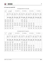
9.8
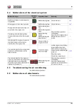
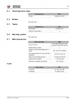
Electrical system
Electrical components
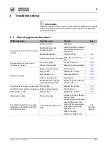
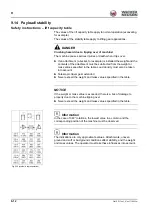
Fuses
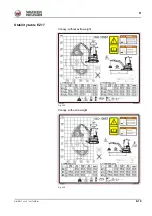
The fuses are located behind the cover, under the seat.
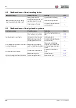
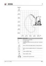
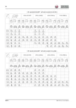
Relays
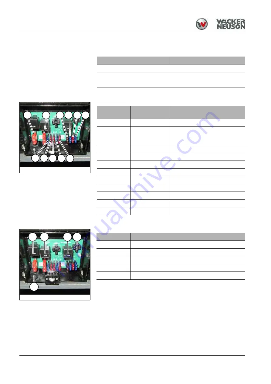
The fuses are located behind the cover, under the seat
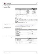
EZ17
Alternator
12 V 55 A
Starter
12 V 1.5 hp (1.1 ) kW
Battery
12 V 30 Ah
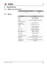
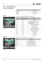
Fig. 222
F2
F1
F4
F3
F7 F8
F5
F10
F9
F6
F11
Fuses
Rated current
(A)
EZ17
F1
50 A
Main fuse
F2
50 A
Main fuse, air-pressure sensor/
output adaptation (Yanmar
3TNV80F-SSNS1)
F3
7.5 A
Display, cutoff solenoid
F4
15 A
Valves, horn
F5
10 A
Proportional controls
F6
10 A
Travel signal, overload
F7
10 A
Boom, cab working lights
F8
15 A
Cab working lights
F9
15 A
No function
F10
15 A
Socket
F11
10 A
No function
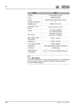
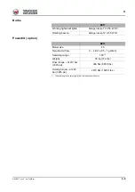
Fig. 223
K7
K8
K9
K58 K17
Relays
EZ17
K7
Starting relay
K8
Cutoff solenoid time lag relay
K9
Cutoff solenoid (pull relay)
K17
Hydraulic quickhitch
K58
High speed (2nd travel speed)
Summary of Contents for EZ17
Page 12: ...1 6 OM EZ17 us 1 0 ez17v100 fm 1 Notes...
Page 38: ...3 10 OM EZ17 us 1 0 ez17e300 fm 3 Warning labels Fig 11 symbolic representation...
Page 43: ...OM EZ17 us 1 0 ez17e300 fm 3 15 3 Labels Fig 24 symbolic representation...
Page 48: ...3 20 OM EZ17 us 1 0 ez17e300 fm 3 Notes...
Page 138: ...5 56 OM EZ17 us 1 0 ez17b510 fm 5 Notes...
Page 146: ...6 8 OM EZ17 us 1 0 ez17t600 fm 6...
Page 198: ...7 52 OM EZ17 us 1 0 ez17w710 fm 7 Notes...
Page 202: ...8 4 OM EZ17 us 1 0 ez17b800 fm 8 Notes...
Page 222: ...9 20 OM EZ17 us 1 0 ez17t900 fm 9 Dimensions Overview EZ17 Fig 227...


