VoloFone™ VF100
User Manual
Copyright © Vololink Pty Ltd 2006-08
V1.1 Jan 2008
Page 8 of 50
VoloFone
™ VF100 Connections
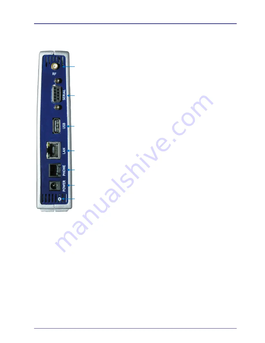
The following diagram shows the rear panel of the VoloFone
™ VF100 and describes the purpose of each
connection.
Antenna (RF)
– attach the supplied antenna to this connector.
Serial port
– this is used for diagnostic/maintenance purposes/reserved for future use.
USB (Universal Serial Bus) port
– this is used for diagnostic/maintenance
purposes/reserved for future use.
Ethernet port (LAN)
– plug a network cable in here. The Link light (green) denotes a
network connection. The Activity light (yellow) denotes network traffic.
Phone port (RJ11)
– connect a phone here.
Power Supply
– connect the power supply cable here.
Reset Button
– Use a paper clip to reset the VoloFone™ VF100. See below for
further information on resetting the VoloFone™ VF100.
Resetting the VoloFone™ VF100
The unit can be reset at any time after the first LEDs sequence appears after a power cycle. This is done by
pressing and holding down the reset button (use a paperclip to do this). The VoloFone
™ acknowledges the
reset button press using its front panel LEDs:
1.
LEDs turn red - first acknowledgment of reset button press.
2.
LEDs turn green - 5 seconds after first acknowledgment.
3.
LEDs turn red again - 10 seconds after first acknowledgement.
The reset button of the VoloFone
™ VF100 has three functions:
1. Reboot the VoloFone
™ VF100
Press and hold the reset button down for a period between the first and second indications; that is, less
than 5 seconds (between the first red LEDs and the green LEDs indication).
This is equivalent to cycling the power of the VoloFone
™ VF100 by unplugging it from the battery base (if
applicable) and unplugging the power supply.


