™
Page 22 of 66
2 vLoc3 RTK-Pro Receiver
2.11.3
The Plan View Screen
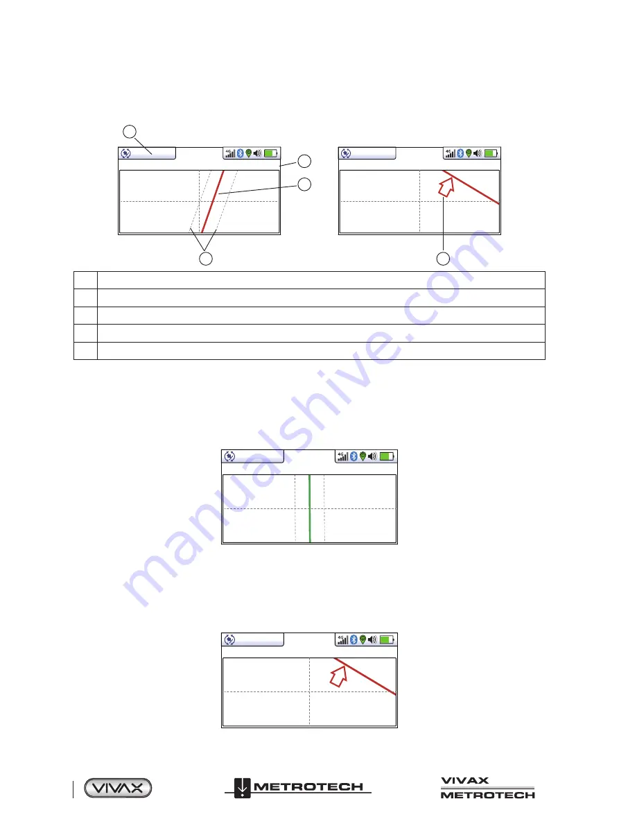
The plan view screen shows a picture as if you were viewing the line from above ground. When the red line is in the center and
pointing forward/backward, you are directly over the line and pointing in the line's direction.
14’5’’
4
3
2
1
12.9mA
32.8kHz
4
G
5
14’5’’
12.9mA
32.8kHz
4
G
1
Depth and current readings
2
Frequency selected
3
Target line
4
Lines of confidence (closer these are to the target line indicates more confidence)
5
Arrow indicates the direction to move towards the line. It only shows when the distance to the target line is far away.
Using the Plan View screen.
1. Apply the signal to the target line in the usual way and select the plan view screen using long presses on the return button
until the desired screen appears.
2. Position the locator within the approximate position of the target line. Use the plan view to help guide you toward the target
line. You can imagine that the plan view is giving you a view into the ground.
3. Position yourself so that the target line is pointing forward/back and is centralized on the screen.
0.18m
3.59mA
32.8kHz
4G
“Tram” lines on either side of the line indicate an area of confidence. The closer the tram lines are together, the greater the
confidence.
In addition to the tram lines, the color of the target line also changes depending on the degree of confidence:
Green
: - low distortion/high confidence.
Blue
: - Minor distortion/medium confidence, proceed with care.
Red
: - Excessive distortion/low confidence. Treat all data and measurements with caution.
4. If the target is off the screen, an arrow will appear on the screen to help direct you to the target line.
-----
32.8kHz
4G
Summary of Contents for 4.04.000170
Page 1: ...vLoc3 RTK Pro User Handbook English Edition Version 1 1 P N 4 04 000170...
Page 2: ......
Page 8: ......
Page 76: ......


