


PowerDome PRO manual V3-6
10
Board Type
Name of Board
Telemetry type
Protocol Board
VPP-RS485
Vista, Pelco D and Pelco P RS485
VPP-Vista -C
Vista Coax
VPP-BBV-C
BBV coax
VPP-PELCO-C
Pelco coax
VPP-PHILIPS
Philips RS422 Telemetry
VPP-AD
AD Manchester code
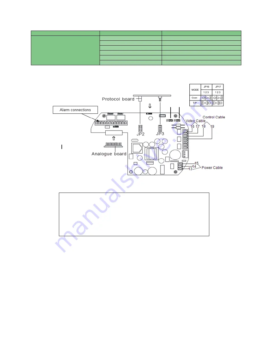
NOTE:
The protocol board should be inserted into JP2 and JP3; these can be found on the hinged power board within the dome
housing.
The above diagram shows the wiring connection point for:
1. Power
– pins 13 and 15, pin 14 is for ground.
2. Video
– Jumpers 16 and 17 ( can be used for Coax or twisted pair –
adjust jumpers shown in table above, coax as default See page 55)
3. Data
– Pins 18 and 19.
4. Alarms
JP16 JP17
Summary of Contents for powerdome pro series
Page 2: ...PowerDome PRO manual V3 6 1...
Page 4: ...PowerDome PRO manual V3 6 3...
Page 9: ...PowerDome PRO manual V3 6 8 Figure 3...
Page 19: ...PowerDome PRO manual V3 6 18 Figure 16 Figure 17 Figure 18 Figure 19 Figure 20 Figure 21...
Page 20: ...PowerDome PRO manual V3 6 19 Figure 22 Figure 23 Figure 24 Figure 25...
Page 32: ...PowerDome PRO manual V3 6 31 Menu Tree Page 4 Privacy setup and Alarm Setup Menus...
Page 81: ...PowerDome PRO manual V3 6 80 Installer Notes...
Page 82: ......


