background image


HDR-5000 User and Technical Manual 

2.4  Installing the HDR-5000 

The HDR-5000 is typically mounted in a standard 19-inch (48.3 cm) rack. Each unit occupies 2 rack units 
(2RU) of height. The cabling is permanently installed and power comes from the facility or site power 
source. This section describes typical mounting and cabling for the HDR-5000; your installation may vary. 

WARNING 


Follow instructions carefully. Do not place the equipment on an unstable support 
such as a cart, stand, or table. The equipment could fall and cause equipment 
damage or cause personal injury.


Mounting the HDR-5000 receiver into an equipment rack is easier if one person holds the unit while 
another person installs the mounting screws. Do the following to set up the components at each receive 
site.


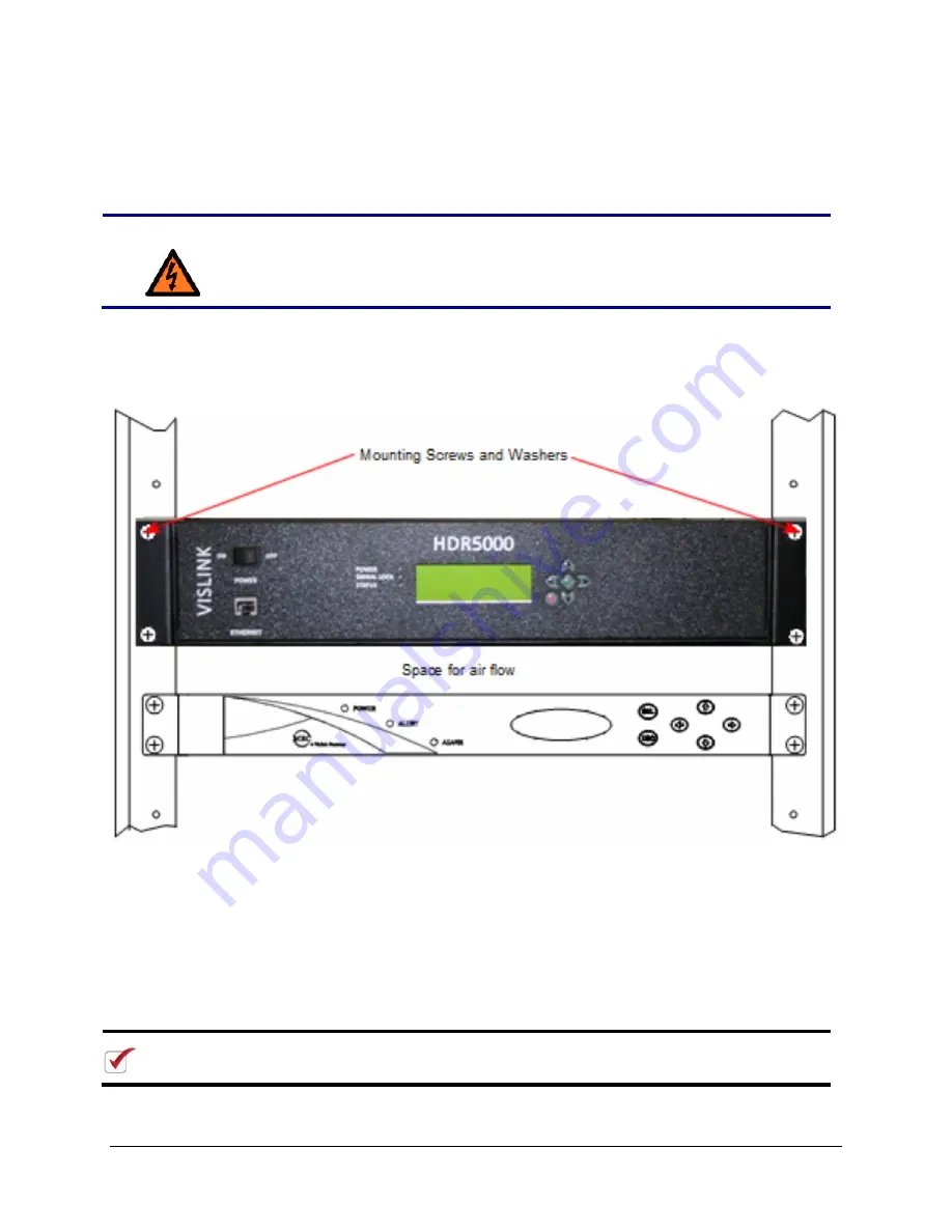
Figure 2-1. Mounting the HDR-5000 Rear Panel (HDR-5000-1/2 model shown) 


1.  Line up the mounting holes on the receiver front panel with the mounting holes on the rack as 

shown in the figure. 

2.  Install the two bottom screws first. Use lock washers to prevent loosening and be sure that the 

fasteners tightened securely. 

3.  Install the top two screws. Use lock washers to prevent loosening. Tighten securely. 

4. Make 

sure 

the 

POWER 

switch is off (

O

). Connect the standard 3-prong power cable to the back 

of the HDR-5000 then connect the other end to the AC power source. An auto-sense circuit 
accepts either 105 to 130 VAC or 205 to 240 VAC, 47 to 63 Hz. 

NOTE:


When installing components, leave 1 RU of space between them for ventilation. 
Also, for non-US applications, you must replace the 3-prong male connector.


Summary of Contents for HDR-5000

Page 1: ...HDR 5000 Six Input Diversity Rack Mounted HD SD Digital Receiver User and Technical Manual Manual Part No RD001485 Rev 2 February 2015 ...

Page 2: ...e requirements and regulations must be observed by personnel operating and maintaining the equipment covered by this manual to ensure awareness of potential hazards This equipment has been tested and found to comply with the limits for a Class A digital device pursuant to Part 15 of the FCC Rules These limits are designed to provide reasonable protection against harmful interference when the equip...

Page 3: ...nstalling Antennas and Block Downconverters 9 2 6 Installing the HDR 5000 9 3 Operating the HDR 5000 11 3 1 Initial Setup 11 3 2 Using the Front Panel Control Screen 11 3 2 1 Viewing the System Name 11 3 2 2 Viewing Channels 11 3 2 3 Viewing and Modifying System Settings 12 3 2 4 Factory Restore 12 3 3 Using the Web Interface 13 3 3 1 Site Management 13 3 3 2 HDR 5000 Login Web Page 14 3 3 3 Unit ...

Page 4: ...ters 25 3 7 4 Remove Encryption Keys 25 3 7 5 Add Encryption Keys 25 3 8 TSoIP Endpoint 26 3 8 1 Edit Transport Stream over IP TSoIP Definition 26 3 8 2 Parameters 26 3 9 System Settings 27 3 9 1 Network 27 3 10 Support 28 3 10 1 System Details 29 3 11 Upgrade System Software Firmware 29 3 12 User Management 33 3 12 1 End User 33 3 12 2 Information 33 3 13 Change Password 34 3 13 1 Edit Password 3...

Page 5: ...SB Connectors 39 5 2 2 Ethernet Connector 39 5 3 Rear Panel Connectors 39 5 3 1 Block Downconverter BDC Connectors 39 5 3 2 ASI OUT Connectors 40 5 3 3 Ethernet Connector 40 5 3 4 AC Power Connection 40 Appendix 1 Specifications for the HDR 5000 41 ...

Page 6: ......

Page 7: ...TE 2022 standard BCRYPT and AES decryption allow the HDR 5000 to interoperate with any COFDM streams using this standardized encryption In the field HDR 5000 diversity receivers are installed at strategic sites to receive the airborne video transmissions passing through the network s coverage area Each receiver sends video data via IP to the network operating center for viewing The HDR 5000 models...

Page 8: ...ht Customizable band plans with BDCs Compatible with low noise Link 3025 model block downconverters Operates on 105 240 VAC 47 63 Hz An auto sensing circuit detects actual line voltage The rear power connector includes a removable fuse holder with fuses 1 1 1 Accessories The HDR 5000 receiver is compatible with several Vislink block downconverters BDCs that transform the incoming RF signal into UH...

Page 9: ...cy of the block downconverters used in the receiver system Vislink has a range of block downconverters and antennas designed for each frequency range Contact Vislink to select the proper BDCs for your receive site including your legacy antennas where feasible 1 2 Front and Rear Panel Layout Figure 1 4 and Figure 1 5 show the layout of the controls indicators and connectors on the front and rear pa...

Page 10: ...tch ON or OFF 2 ETHERNET RJ 45 This connection allows you connect the receiver to a computer to control it using the HDR 5000 Web interface 3 LED Indicators Power Green Power applied Signal Lock Demod COFDM Lock Red No Demod Lock Green Demod Lock Status Red Current Fault Condition Green All good 4 MONITOR display 3 5 inch LCD Displays text based status 5 Keypad These arrow buttons allow scrolling ...

Page 11: ...in the case of a fault or the terminus on a protective earth electrode 3 BDC1 BDC2 BDC3 BDC4 BDC5 BDC6 The BDC TNC block downconverter connectors accept UHF signals from the block downconverters and their corresponding antennas To power each downconverter 18 5 VDC is applied to the coaxial cable that runs from the BDC connector to the downconverter 4 COMPOSITE VIDEO PREVIEW HDR 5000 3 only Passes ...

Page 12: ...age report to Vislink Customer Service Contact Vislink Customer Service to determine the disposition of the equipment See Chapter 4 Troubleshooting 2 2 Preparing to Install the HDR 5000 The following sections describe the things you should consider before installing the HDR 5000 2 2 1 Grounding the HDR 5000 For safe operation all equipment must be properly grounded Connect all equipment on a rack ...

Page 13: ... an obstruction Provide flex relief at any location where the cable must change direction sharply to maintain a smooth bend and prevent kinking Provide strain relief at each connector to absorb any pulling forces on the cable and prevent damage to the connector If long lengths of cable are required you may need a UHF amplifier or gain block Contact Vislink for specific cable types and lengths to u...

Page 14: ...installs the mounting screws Do the following to set up the components at each receive site Figure 2 1 Mounting the HDR 5000 Rear Panel HDR 5000 1 2 model shown 1 Line up the mounting holes on the receiver front panel with the mounting holes on the rack as shown in the figure 2 Install the two bottom screws first Use lock washers to prevent loosening and be sure that the fasteners tightened secure...

Page 15: ...vel is received by the UHF cable as though it is an antenna and causes the HDR 5000 to operate improperly or not at all 2 6 Installing the HDR 5000 Minimum distance between any two antennas and proper alignment are critical for optimum performance You should initially install the antennas at the recommended minimum separation distance If necessary increase the distance by quarter wavelengths The f...

Page 16: ...3 Attaching the Antenna to the BDC RF INPUT Connectors You can install a pair of antennas that are each directly connected to a BDC on a vertical pole assembly by doing the following 1 Fasten the first BDC onto the mounting pole and secure it firmly in position using the mounting bracket and heavy duty band clamp 2 Connect the first antenna securely to the BDC RF INPUT connector 3 Determine the mi...

Page 17: ...ay Signal Lock LED will be lit green when the HDR 5000 is properly receiving your transmitter s signal If you have any problems see Chapter 4 Troubleshooting 3 2 Using the Front Panel Control Screen The Front Panel Control Screen displays the following information Static or DHCP IP address subnet mask Default gateway of the HDR 5000 Current Preset Current Frequency Your unique HDR 5000 receiver na...

Page 18: ... gateway address 4 D1 This line displays the HDR 5000 receiver s current primary Domain Name Server DNS address To view or edit the secondary DNS address D2 use the Right Arrow button 5 D2 This line displays the HDR 5000 receiver s current secondary Domain Name Server address Figure 3 1 Front Panel Control Screen Operation 3 2 4 Factory Restore Since the user has the ability to edit username and p...

Page 19: ...ol Screen Operation figure shows the Control Web UI with 6 incoming signals The callout text shows how the Dashboard Web UI is organized Use the keypad to highlight areas of the Control Web UI and press OK to display a settings Web UI for the highlighted parameter or open a one of the other setting Web UIs Presets Setup Options or Monitor 3 3 1 Site Management When you first attempt to engage the ...

Page 20: ...administrator 3 3 2 HDR 5000 Login Web Page Type the HDR 5000 IP address in a Web browser to display the Login Web page The default user ID and password is root This page also appears when you select the Logout tab in any of the Web pages allowing you to reenter your user name and password or login a new user Refer to the sample Web page shown below The HDR 5000 Web interface can be accessed from ...

Page 21: ...oard page Select Setup located in the top menu and then select Channel Plans located on left side of screen 3 3 5 Channel This field displays the current Channel name bandwidth and frequency You are able to select an alternate channel for the current preset by using the Set Channel drop down displayed in the Dashboard page You can also create a new channel using the Channel Plan Web interface page...

Page 22: ...nked to the HDR 5000 The demodulation Signal to Noise Ratio to Received Signal Strength Indication is dynamically displayed as follows 5 displays a red bar graph 5 10 displays an amber bar graph 10 displays a blue bar graph 3 3 10 Modulation Status The Modulation Status fields show information about demodulated signal Modulation Mode This field displays the Modulation Mode selected for the current...

Page 23: ...isy communication channels This DVB T FEC is set by the transmitter The receiver auto detects the settings used by the transmitter The FEC values include 1 2 2 3 3 4 5 6 7 8 Guard Interval The Guard Interval is a method used to prevent interference within distinct transmissions The Guard Interval auto detected by the transmitter is displayed in this field The Guard Interval values include 1 32 1 1...

Page 24: ...trol of the HDR 5000 can be stored within a preset to be recalled at any time during routine operation An unlimited array of presets can be saved and accessed using the Web interface Each preset encompasses TSoIP configuration Encryption settings BDC selection dictating available frequencies Frequency channel selection providing a choice of reception frequency NOTE You can change any of these para...

Page 25: ...lans BDCs TSoIP Endpoints System Settings and if needed Encryption Keys Once you have created these custom parameters add Presets that you can use and modify to receive high quality video and audio feed from your transmitters Figure 3 6 Presets Page 3 4 2 Parameters Name This field displays the current or selected preset s name ...

Page 26: ...yption Definition section Within the Presets page you can use the Select Encryption drop down to select existing Channel configurations 3 4 7 TSoIP1 and 2 Configuration The Transport Stream over Internet Protocol TSoIP sets the destination of the video signal across the IP network The TSoIP parameters can be set in the TSoIP Endpoint Web interface The primary and the secondary TSoIP settings that ...

Page 27: ...hree default BDC definitions or create a new configuration with the Create New button This page provides a means to configure the BDC name model frequency range and local oscillator frequency The BDC parameters for the preset can be edited in the BDC Web interface page under the Edit BDC Definition section Within the Presets page you can use the Select BDC drop down to select existing BDC configur...

Page 28: ...r a Channel Name a Band Width BW and a channel Frequency expressed in MHz To add an alternate channel click the button Select the Save Changes button to create the New Channel Plan 3 6 2 Edit Copy Delete Channel Plans These fields display the existing Channel Plan names with an Edit button that allows you to modify the listed plans including bandwidth and frequency You are able to hide a channel p...

Page 29: ...encryption keys within the Add Encryption Keys section After you create a key you must click the Save Changes button to add it to the HDR 5000 system To delete existing Encryption Keys use the button in the Remove Encryption Keys listing of all the existing keys When you click the Create New drop down you will be able to add a new Encryption Key using the Add Encryption Keys section Encryption par...

Page 30: ...PIDs Figure 3 9 Encryption Page 3 7 1 Steps to Create a New Encryption Key To define a new Encryption Key go to the fields in the Encryption Key page found at the bottom of the page in the section titled Add Encryption Key and populate these fields 1 Click within the Name field in the Add Encryption Keys section and type a unique easily recognized description for the specific Encryption Key for in...

Page 31: ...The Encryption Key field displays the selected Encryption Definition PIDs The Packet Identification PIDs associated with the Encryption Definition are listed below the Key field You can delete a listed PID when you click the button Auto Mode When you select Auto Mode On the system will automatically use these values to determine which PIDS in the transport stream to decrypt for the selected Encryp...

Page 32: ...3 10 TSoIP Endpoint Page 3 8 1 Edit Transport Stream over IP TSoIP Definition The Edit TSoIP Definition provides a means to select the Transport Stream over IP parameters when you use the drop down menu You can also click the Create New button to set up an alternate target IP address and port via UDP or RTP to send video signals across the IP network 3 8 2 Parameters The Parameters section provide...

Page 33: ...nfiguration Protocol On to configure the HDR 5000 receiver s IP address Set your own IP address by not enabling DHCP Off to use a Static IP Type or change to DHCP Enable On to automatically set the IP address subnet mask gateway and DNS server addresses from your DHCP server IP Address The Internet Protocol Address that is used by the HDR 5000 receiver can be modified by not selecting the DHCP Ena...

Page 34: ...modified when DHCP is enabled When DHCP Enable is not selected Off you can modify the Domain Name Server address to match settings provided by your network administrator Click Save Changes to retain the newly selected IP Addresses 3 10 Support HDR 5000 Support tab provides a means to locate information for your HDR 5000 that a LiveGear support expert will use as a reference to get started alleviat...

Page 35: ...software and hardware versions for both encapsulator 1 and 2 Crypto The Crypto field displays the software version for the security software 3 11 Upgrade System Software Firmware When Vislink ships your new HDR 5000 the latest version of the system software firmware is installed Periodically we release updates and recommend that you install these You can download these updates at our FTP site To a...

Page 36: ...k for the latest firmware file which has the deb extension Click on this file to download it and note where you saved it on your computer Then proceed with the steps below 5 In the HDR5000 web interface click SUPPORT in the toolbar at the top of the page Then click the Software Upgrade tab in the left column The Upgrade System Software page displays ...

Page 37: ...k the Choose File Upgrade button to open Windows Explorer and select the firmware file you downloaded from Vislink s FTP site 7 The following message displays on the Upgrade System Software page as the firmware is updated on your HDR 5000 device ...

Page 38: ...32 HDR 5000 User and Technical Manual 8 When the firmware update is finished the login screen displays Log in again by entering your username and password and clicking the Log In button ...

Page 39: ...rs Figure 3 14 User Management Page 3 12 1 End User To Edit or Delete an existing user select the name from the drop down list and proceed to the Information section To create a new user use the Create New button 3 12 2 Information To create a new user type a unique Username and Password Confirm the password by typing it into the Repeat Password entry field Next select a Role which classifies the ...

Page 40: ...urrent user name and Select the Change Password option Figure 3 15 Change Password Page 3 13 1 Edit Password To Edit Password for the current user perform the following 1 Old Password First type the old password 2 New Password Next type the new password 3 Repeat New Password Finally re enter the new password for confirmation and click the Change Password button to finish the process ...

Page 41: ...he bottom of each unit Approximate purchase date Firmware revisions of the options contained in your receiver You can obtain these as follows 1 Select Support on the Web Dashboard page 2 The Support page lists installed hardware and software components and revision levels NOTE There are no supported field repairs to the HDR 5000 system Return the unit for factory repair CAUTION If you attempt fiel...

Page 42: ... condition of all antennas BDCs and the cables connected to them Make sure power cable is firmly t d t b th d Poor video quality Signal strength is low due to interference or a weak signal Receive antennas in use are not in the transmitter s line of sight Interference problem Determine if the remote crew can relocate or reposition the transmitter switch to another channel or boost power Determine ...

Page 43: ...he following table described suggested actions to general system problems Problem Possible Cause Suggested Actions Cannot connect to the web server Receiver is powered down or disconnected from the network Verify that the receiver is powered up and that it is connected to the network Receiver IP address is incorrect From the Control screen select use the arrow buttons and select the IP Address con...

Page 44: ...his appendix contains connector specifications for your HDR 5000 Six Input Rack Mounted HD SD Digital Receiver 5 1 HDR 5000 Dimensions The following figure shows the HDR 5000 dimensions in inches 16 972 x12 031 x 3 490 Figure 5 1 Dimensions of the HDR 5000 in Inches ...

Page 45: ...and use the receiver s Web browser interface to control the receiver Connector Pinout Signal Description Pin 5 3 Out Signal Description 8 1 1 TX 5 not used 2 TX 6 RX 3 RX 7 not used 4 not used 8 not used 5 3 Rear Panel Connectors The following sections describe the HDR 5000 back panel connectors Figure 1 5 shows the rear panel connectors 5 3 1 Block Downconverter BDC Connectors The BDC block downc...

Page 46: ...computer and use the receiver s Web browser interface to control the receiver Connector Pinout Signal Description Pin 5 3 Out Signal Description 8 1 1 TX 5 not used 2 TX 6 RX 3 RX 7 not used 4 not used 8 not used 5 3 4 AC Power Connection The unit has a standard IEC connector The AC receptacle is protected by a pair of 2 amp fuses The power supply accepts a range of AC input voltages from 105 240 ...

Page 47: ...System Control Via RJ 45 Ethernet Connection USB 2 available ports POWER AC Power Input 120 240 VAC 50 60 Hz Power Consumption Less BDCs 28 Watts CONFIGURATION HDR 5000 Six Input Diversity HD SD 5000 1 provides 1 IP output and 1 ASI output 5000 2 provides 2 IP outputs Please contact your sales representative for additional details FREQUENCY PARAMETERS Band Support 1 785 7 125 BDC Dependent Frequen...

Reviews: