Appendix
85
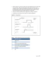
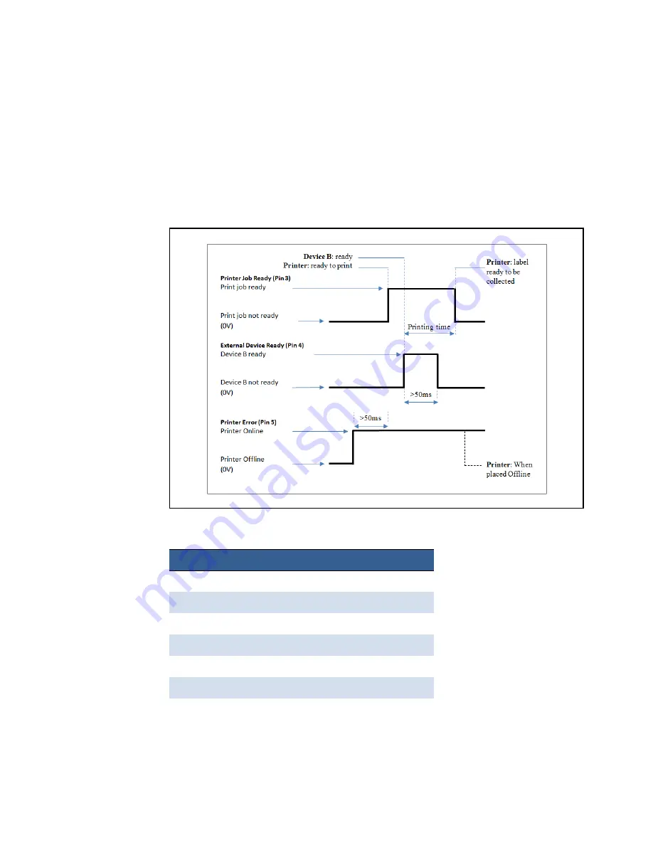
• Device B signals it is ready by pulling up the Ready signal. This must remain high
for at least 50 ms. When the Ready signal is pulled down while the printer is
printing, the printer will pause and behave exactly the same way as if the user
presses the Pause button on the control panel. The printer remains in Pause
mode until the Ready signal is pulled up again for at least 50ms.
• The printer prints and pulls down the signal when printing is completed.
• No printing occurs whenever the Printer Error signal is pulled low.
Figure 11
Timing Diagram
Table 7
GPIO Pin Assignment (D‐sub 9‐pin Connector)
Pin
Signal Description
1
HIGH (3.3 V)
2
ADC 5
3
Print job ready (output) (GPIO A25)
4
External device ready (input) (GPIO D04)
5
Printer error (output) (GPIO D08)
6
LOW (0 V)
7
NC
Summary of Contents for VP7 Series
Page 1: ...VIPColor U s e r G u i d e VP7xx Printer Series ...
Page 8: ......
Page 9: ......
Page 10: ......
Page 11: ......
Page 12: ......
Page 16: ......
Page 17: ......
Page 18: ......
Page 19: ......
Page 20: ......
Page 21: ......
Page 22: ......
Page 24: ......
Page 26: ......
Page 27: ......
Page 28: ......
Page 29: ......
Page 45: ......
Page 46: ......
Page 47: ......
Page 48: ......
Page 49: ......
Page 50: ......
Page 52: ......
Page 53: ......
Page 54: ......
Page 55: ......
Page 56: ......
Page 57: ......
Page 58: ......
Page 59: ......
Page 60: ......
Page 61: ......
Page 62: ......
Page 63: ......
Page 64: ......
Page 70: ......
Page 73: ......
Page 75: ......
Page 76: ...76 Troubleshooting ...
Page 78: ......
Page 83: ......

