53
4
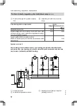
Heating circuit pump A1
5
Heating circuit with mixer M2 (heat-
ing circuit 2)
6
Flow temperature sensor M2
7
Heating circuit pump M2
8
Extension kit for one heating circuit
with mixer M2
9
Heating circuit with mixer M3 (heat-
ing circuit 3)
qP
Temperature limiter for limiting the
maximum temperature of underfloor
heating systems
Flow temperature sensor M3
qW
Heating circuit pump M3
qE
Extension kit for one heating circuit
with mixer M3
qR
Low loss header
qT
Flow temperature sensor, low loss
header
Function/system components
Code
Adjust Delivered con-
dition
Operation with LPG
82:1
82:0
System
only
with two heating circuits with mixer with
extension kit for mixer (without unregulated heating
circuit) with DHW heating
00:8
00:10
Heating circuit pump A1 connection at extension
AM1, terminal A1
—
33:1
DHW circulation pump connection at extension AM1,
terminal A2
—
34:0
Adjusting the heating curves (only for weather-compensated
control units)
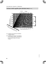
The heating curves illustrate the relation-
ship between the outside temperature
and the boiler water or flow tempera-
ture.
To put it simply, the lower the outside
temperature, the higher the boiler water
or flow temperature.
The room temperature, again, depends
on the boiler water or the flow tempera-
ture.
Note
If the heating system includes heating
circuits with mixers, then the flow tem-
perature of the heating circuit without
mixer is higher by a selected differential
(8 K in the delivered condition) than the
flow temperature of the heating circuits
with mixers.
The differential temperature can be
changed at coding address 9F.
Settings in the delivered condition:
■ Slope = 1.4
■ Level = 0
Commissioning, inspection, maintenance
Further details regarding the individual steps
(cont.)
5457 552 GB
Service
Summary of Contents for FS2B
Page 163: ...163 5457 552 GB ...


