


66250010-EN - V2.0 - 24/09/18
10
Telephone Interface Module
Art. 380N/UK Telephone Interface Module - Installation Instructions
General Directions for Installation
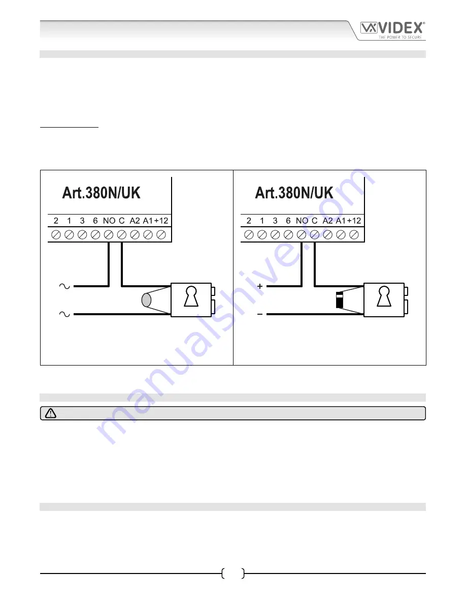
LOCK RELEASE WIRING AND BACK EMF PROTECTION
In most cases when connecting an
Art.380N/UK
to a Videx intercom system the electric lock release would be connected directly
from the intercom door station (refer to the wiring diagrams on pages 19 - 22 for examples). It is however possible to connect the
lock release directly through the relay contacts
C/NO
on the
Art.380N/UK
if the need arises.
When fitting the lock release through the relay contacts
C/NO
back EMF protection will be required. If fitting an AC lock release then
a 100nF ceramic disc capacitor must be fitted across the terminals of the lock, shown in
Fig.10
. If fitting a DC lock release (fail secure
or fail safe) then a 1N4002 diode must be fitted across the terminals on the lock, shown in
Fig.11
.
IMPORTANT NOTE: A separate power supply capable of powering the lock will be required whether fitting an AC lock (fail
secure) or when fitting a DC lock (fail secure or fail safe).
It should also be noted that if a fail safe lock is being connected the Art.380N/UK relay will need to be programmed for C/NC
(common normally closed) operation using the programming code 101, refer to onboard relay reversal (C/NO or C/NC) notes
on page 14.
12V AC
FAIL SECURE
LOCK RELEASE
12Vac
input
100nF CAP
(or 14-20V MOV)
12V DC
FAIL SECURE
OR FAIL SAFE
LOCK RELEASE
12Vdc
input
1N4002
DIODE
Fig. 10
Fig. 11
If a 100nF ceramic disc capacitor or a 1N4002 diode are not available then a 14 - 20V MOV (metal oxide varistor) can be fitted across
the lock terminals instead. The MOV can be fitted on both an AC and DC lock and is not polarity conscious, follow
Fig.10
for wiring.
CONNECTION TO MAINS, SAFETY AND GUIDANCE NOTES
IMPORTANT: PLEASE READ THESE INSTRUCTIONS CAREFULLY BEFORE COMMENCING WITH THE INSTALLATION.
Videx recommends that any cabling and Videx product be installed by a competent and qualified electrician, security installation
speclialist or communications engineer.
• DO NOT
install any Videx product in areas where the following may be present or occur:
• Excessive oil or a grease laden atmosphere.
• Corrosive or flammable gases, liquids or vapours.
• Possible obstructions which would prevent or hinder the access and/or removal of the Videx product.
MAINS CONNECTION
The system
MUST
be installed in accordance with the current I.E.E regulations (in particular
I.E.E. Wiring regulations BS7671 for the
UK
), or the appropriate standards of your country, in particular Videx recommends:
• Connecting the system to the mains through an all-pole circuit breaker (refer to
Fig.12
) which shall have contact separation
of at least 3mm in each pole and shall disconnect all poles simultaneously.