background image

Chapter 3 Installing CPRIAdvisor CAP-100 and CAE-100 


CPRIAdvisor Installation Guide 

29


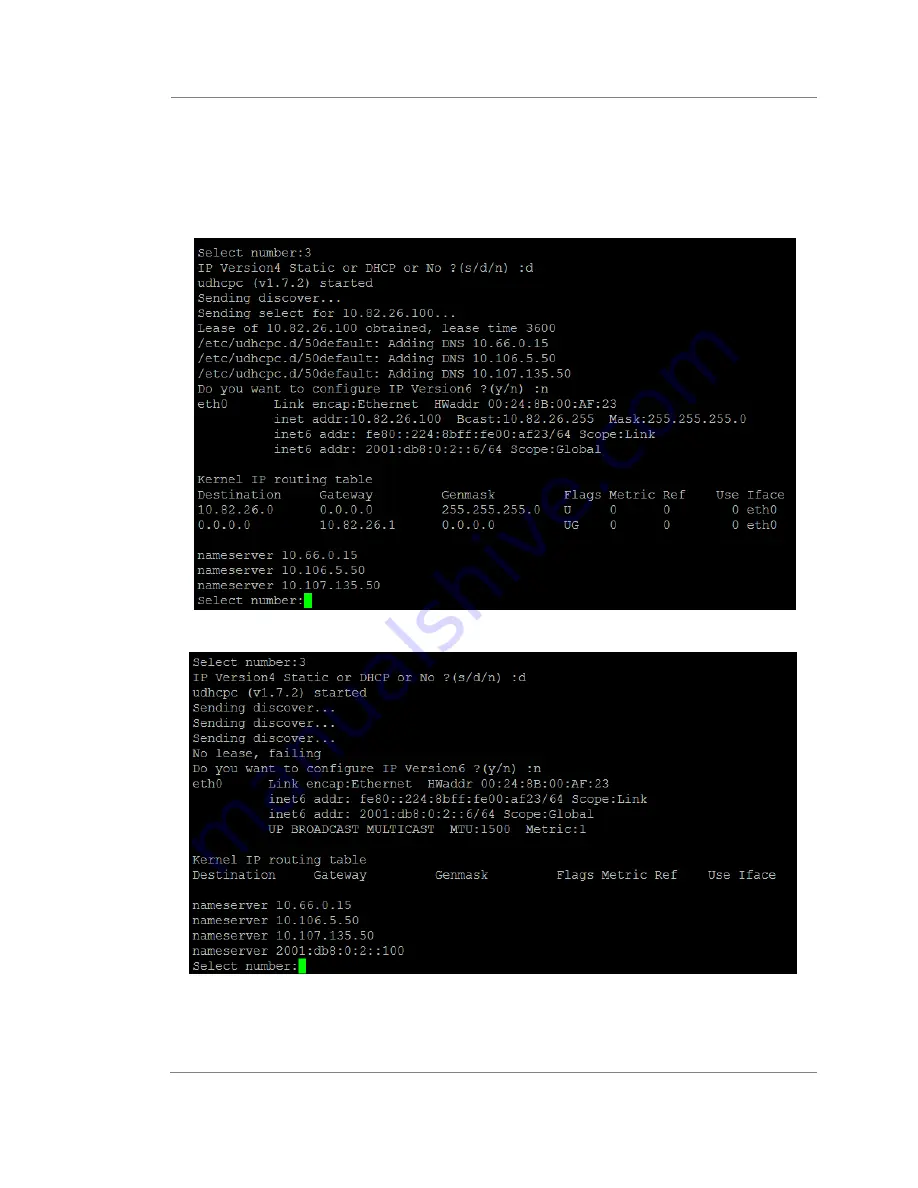
You need to select Ethernet Configuration. Type 3 in Select number. 

If you want to enable automatic IP addressing, type d between the three choices: s, d or 
n. 

10 

The following two on-screen prompts appear. 

Assigned an IP address 


Failed to assign an IP address 


11 

If you type n in 

step 9

,


you can confugure IP verrsion6. 

12 

Type IP V6 addess, length, gateway and DNS. 

13 

The following on-screen prompt appears. 

Summary of Contents for CPRIAdvisor CAE-100

Page 1: ...CPRIAdvisorTM Version 1 0 Installation Guide ...

Page 2: ...CPRIAdvisorTM Version 1 0 Installation Guide Viavi Solutions 1 844 GO VIAVI www viavisolutions com ...

Page 3: ...soft Corporation in the United States and or other countries Copyright release Reproduction and distribution of this document is authorized for Government purposes only Open source disclaimer IMPORTANT READ CAREFULLY The JD720C Series includes third party software licensed under the terms of separate open source software licenses By using this software you agree to comply with the terms and condit...

Page 4: ...Directive 2014 30 EU and its amending directives for electromagnetic compatibility Conformity with this directive is based upon compliance with the harmonized European standard EN61326 1 A copy of the Declaration of Conformity is provided upon your request Low voltage directive compliance This product was tested and conforms to the Low Voltage Directive 2014 35 EU and its amending directives Confo...

Page 5: ...g the CPRIAdvisor CAP 100 15 Front view 16 Rear view 17 Exploring the CPRIAdvisor CAE 100 18 Front view 18 Rear view 19 Installing the CPRIAdvisor CAP 100 19 Installing the CPRIAdvisor CAE 100 22 Grounding the CPRIAdvisor CAP 100 25 Grounding the CPRIAdvisor CAE 100 26 Connecting your CPRIAdvisor CAP 100 via Serial 26 Setting date and time 30 NTP setting recommended 30 Manual setting 32 Upgrading ...

Page 6: ...de 6 CPRIAdvisor Installation Guide 1 Chapter 1 About This Guide Topics discussed in this chapter include the following Purpose and scope 7 Assumptions 7 Safety and compliance information 7 Conventions 7 Technical assistance 9 ...

Page 7: ...is product yourself as opening or removing covers may expose you to dangerous voltage and other hazards Refer all servicing to qualified Viavi service personnel CAUTION This equipment contains parts and assemblies sensitive to electrostatic discharge ESD Use ESD precautionary procedures when touching removing or inserting ESD sensitive parts and assemblies or damage to components could result An e...

Page 8: ... that includes important supplemental information or tips related to the main text This symbol represents a general hazard It may be associated with either a DANGER WARNING or CAUTION message This symbol represents hazardous voltages It may be associated with either a DANGER WARNING or CAUTION message This symbol represents a risk of explosion It may be associated with either a DANGER WARNING or C...

Page 9: ...eral hazard high voltage or risk of explosion symbol When applied to software actions indicates a situation that if not avoided could result in loss of data or a disruption of software operation Technical assistance If you require technical assistance call 1 844 GO VIAVI or send an email to TAC viavisolutions com For the latest TAC information go to http www viavisolutions com en services and supp...

Page 10: ...roduction to CPRIAdvisor CAP 100 and CAE 100 This chapter provides a general description of the CPRIAdvisor CAP 100 and CAE 100 Topics discussed in this chapter include the following CPRIAdvisor CAP 100 and CAE 100 11 Features 11 Specifications 11 ...

Page 11: ...00 can control up to 16 CAE 100 to expand the optical input capacity up to 576 optical ports Using CAM 100 you can easily track down the source of interference by comparing spectrum of multiple impacted sectors Features Up to 10K of CPRI profiles in CAP 100 to allow auto configuration and spectrum Profile DB back up enables faster mass installation and easier maintenance Layer 2 alarm monitoring O...

Page 12: ... MHz ref input Frequency reference GPS antenna Frequency reference Power Supply Input voltage range 60 to 36V Power supply 72W Environment Operation 0 C to 40 C Storage 20 C to 60 C Humidity 5 to 95 without condensing Vibration MIL PRF 28800F Class 3 Shock MIL PRF 28800F Class 3 Inflammability UL94 V1 or above Table 5 General specifications for CPRIAdvisor CAE 100 Item Descriptions Mechanical Heig...

Page 13: ...Guide 13 Input voltage range 8 to 15V Power Supply Power consumption 72W Operating 0 C to 40 C operating temperature range Environment Storage 20 C to 60 C Humidity 5 to 95 without condensing Vibration MIL PRF 28800F Class 3 Shock MIL PRF 28800F Class 3 Inflammability UL94 V1 or above ...

Page 14: ...ssed in this chapter are as follows Unpacking the CPRIAdvisor CAP 100 and CAE 100 15 Exploring the CPRIAdvisor CAP 100 15 Exploring the CPRIAdvisor CAE 100 18 Installing the CPRIAdvisor CAP 100 19 Installing the CPRIAdvisor CAE 100 22 Grounding the CPRIAdvisor CAP 100 25 Grounding the CPRIAdvisor CAE 100 26 Connecting your CPRIAdvisor CAP 100 via Serial 26 Setting date and time 30 ...

Page 15: ... items in the package Table 6 Items included Item Quantity CPRIAdvisor CAP 100 1 Screw 8 for bracket mounting Serial cable 1 Cross LAN cable 1 USB A to B cable 1 1 GB USB memory containing CPRIAdvisor User s Manual and Software Application 1 Lock washer 1 Bracket 2 A basic set of the CPRIAdvisor CAE 100 should include the following items in the package Table 7 Items included Item Quantity CPRIAdvi...

Page 16: ...AE 100 by connecting a control cable from this port to the Control in port of the CAE 100 Serial port You can use this port to enable maintenance and set up CAP 100 initially by configuring an IP address LAN port You can use this LAN port to connect the CAP 100 to your network and control CAP 100 remotely using the application software CAM 100 USB client port This port is reserved for future usage...

Page 17: ...s used to connect grounding of the CAP 100 48 VDC port This port is used to supply the external power 48 VDC Power switch You can use this switch to turn your CAP 100 on and off Rear view Figure 2 CPRIAdvisor CAP 100 rear view No Description Optical input port Optical input port You can use this port to connect optical LC cable The CAP 100 has 16xLC optical ports CAUTION Do not apply or connect po...

Page 18: ...Service port Reset Grounding connection Control out port You can use this port to connect the CAE 100 via cascading It transmits control commands from the CAP 100 to CAE 100 Control in port You can use this port to communicate with the CAP 100 ID number It is used to assign a unique ID to CAE 100 ID range 0 15 For more detailed ID number setting you can refer to the following figure Service port Y...

Page 19: ...this COM port NOTE You need to connect the COM port to an optical port that is positioned in the same location of ID 1 of the CAE 100 Optical input port You can use this port to connect the optical LC cable You can connect 36xLC optical ports per each CAE 100 Installing the CPRIAdvisor CAP 100 After inspecting your shipment follow the procedure below to install the CPRIAdvisor CAP 100 Procedure To...

Page 20: ...d The bracket size is longer than the one in the 19 inch rack 2 Mount the CAP 100 to both ends of a 23 inch rack NOTE The cabinet model RBS6101 and RBS6120 require mid mount brackets which are inversely mounted to the CAP 100 due to space limit To install 16xLC to 24xMPO adapter pannel Optional 3 Mount the MPO adapter panel to the frontal side of one of the two empty slots in the 19 inch shelf ...

Page 21: ... panel 5 Connect the 16 LC connectors to each 16 optical input ports on the rear of the CAP 100 6 Connect a LAN cable and a 48 VDC input power cable to the CAP 100 Make sure you connect input and return correctly Battery Return BR should be treated as an isolated dc return DC I 7 Connect the optical cable to the rear of each 16 ports of the CAP 100 ...

Page 22: ... the green LED illuminated 10 Connect the uplink interface port of the coupler to the CPRIAdvisor CAM 100 NOTE Once the installation of the CAP 100 is complete you need to set IP address date and time via Serial before connecting to CAM Installing the CPRIAdvisor CAE 100 After inspecting your shipment follow the procedure below to install the CPRIAdvisor CAE 100 Procedure To install with a 19 inch...

Page 23: ...ely attached to the CAE 100 due to space limit To install with a 23 inch rack 1 Using a Phillips head screwdriver install the brackets with screws provided The bracket size is longer than the one in the 19 inch rack 2 Mount the CPRIAdvisor CAE 100 to a 23 inch shelf inserted under the CAP 100 To install 36xLC to 36xMPO adapter pannel Optional 3 Mount the MPO adapter panel to the frontal side of on...

Page 24: ...5 Connect the 36xLC connectors on the other side to 36 optical input ports aligned with the number in the label on the rear of the CAE 100 6 Connect a DIN cable to the Exp Ctrl port or the upper layer CAP 100 or Control out port of upper layer CAE 100 7 Connect each optical cable from an COM port of the CAE 100 to the designated optical input ports of the CAP 100 based on the CAE 100 ID ...

Page 25: ...skip the in structions above regarding this Grounding the CPRIAdvisor CAP 100 The CPRIAdvisor CAP 100 must be grounded to the building s earth ground system It is suitable for installation as part of the Common Network Bonding CBN The symbol appears on the CPRIAdvisor system shelf to indicate a ground conductor terminal Follow the procedure below to ground the CPRIAdvisor CAP 100 Procedure 1 Fit a...

Page 26: ...her end of the grounding cable to the building s earth ground system NOTE A grounding cable is required when grounding the CAP 100 and CAE 100 However it is not included in the shipment Connecting your CPRIAdvisor CAP 100 via Serial To configure an IP address connect a Serial cable to the Serial port after installing the CAP 100 Using a terminal emulator program such as Tera Term and puTTy you can...

Page 27: ...Ethernet Configuration Type 3 in Select number 9 If you want to assign a fixed IP version4 address type s between the three choices s d or n If you type n follow the step 12 below 10 Type an IP address manually 11 Type a Net Mask and Gateway manually 12 If you want to configure an IP Version6 type y otherwise type n 13 If you type y type an IP V6 address manually 14 Type the IP V6 length manually ...

Page 28: ...ram 4 Set the proper COM port from the terminal emulation program configuration 5 Set the Baud Rate to 115200 Data to 8bit Parity to none Stop to 1bit and Flow Control to none 6 In Windows Device Manager look for the serial port assigned correctly to your PC and note the COM number for example it may appear as COM1 7 If all setting values above are correctly input the following on screen prompt ap...

Page 29: ...ct number 9 If you want to enable automatic IP addressing type d between the three choices s d or n 10 The following two on screen prompts appear a Assigned an IP address b Failed to assign an IP address 11 If you type n in step 9 you can confugure IP verrsion6 12 Type IP V6 addess length gateway and DNS 13 The following on screen prompt appears ...

Page 30: ...er operates well Setting date and time You can set date and time based on your time zone after configuring the IP address The system clock can be set in the format of YYYYMMDD based on your time zone using the terminal emulation program NTP setting recommended You can set date and time by typing the time server on your network The date and time are synchronized with the server Procedure 1 On the o...

Page 31: ...100 CPRIAdvisor Installation Guide 31 3 Select a proper location based on your time zone 4 Select a country that matches with your time zone For example 23 if you are in South Korea 5 If the time zone appeared in the on screen prompt is correct type 1 ...

Page 32: ...y set date and time Procedure 1 On the on screen prompt of the terminal emulator program type 4 2 Type m when asked Date and Time Manual or NTP in the on screen prompt 3 Type year month day respectively based on your time zone You need to set date in the format of YYYYMMDD 4 Type hour 00 23 minute 00 59 second 00 59 respectively based on your time zone 5 The on screen prompt appears as below ...

Page 33: ...ownload it if any newer version is available Installing a new firmware To update your firmware you can choose one of the following 3 ways using your USB memory drive accessing the CAM 100 or using the terminal emulator program Refer to the CPRIAdvisor Manager Help for the second option Upgrading from USB memory drive Procedure 1 Turn the CAP 100 on using Power switch 2 Plug in the USB memory drive...

Page 34: ...he proper COM port from the terminal emulation program configuration 4 Set the Baud Rate to 115200 Data to 8bit Parity to none Stop to 1bit and Flow Control to none 5 Plug in the USB memory drive to the USB Host port of the CAP 100 6 Select 96 in the on screen prompt and type y 7 Select the firmware file you want to upgrade and type y 8 The upgrade process is indicated in the on screen prompt 9 If...

Page 35: ...CAM 100 This chapter provides instructions on how to configure CAP 100 properly to check and obtain accurate monitoring results Topics discussed in this chapter are as follows Installing the CAM 100 36 Connecting CAP 100 via CAM 100 36 Setting up CAP 100 via CAM 100 37 ...

Page 36: ...roperly you can view accurate monitoring results via CAM 100 Procedure 1 Install the CAM 100 saved in the USB drive provided on your computer 2 On your computer double click the CPRIAdvisor Manager icon 3 The main window appears as below Connecting CAP 100 via CAM 100 The main window consists of three panes There are two panes on the left Probe Connection Management and Probe Information Managemen...

Page 37: ...make sure to check your LAN cable is properly connected to Probe and PC If you have more than 2 adapters make sure to check your network adapter connected to the Probe is the same as the one appeared in the Communication from the menu bar Setting up CAP 100 via CAM 100 To view an accurate monitoring result you need to set up your CAP 100 with specific values based on your installation environment ...

Page 38: ...om the three choices to configure your Probe To Configure only Probe without Expansion 5 The following Probe information initialization window appears 6 If you want to configure all pysical ports select All ports from the drop down list and select profile numbers you want to set based on your environment for example 4 NOTE The number of profiles you select is based on the number of antenna carrier...

Page 39: ...uide 39 7 If you click the Apply button the Probe initialization is completed To Configure Probe with Expansion 8 Select Expansion from the drop down list of Physical Port 01 for example All Physical Ports need to be set to None ...

Page 40: ...on window for example 4 NOTE If you want to check information of all ports or all Expansions you can select All Ports or All Expansions from the drop down list You can also select the number of profiles for each port from the drop down list 10 If you click the Apply button the Probe and Expansion initialization is completed CAUTION After you complete the initialization previously set values are al...

Page 41: ...ds are read only The values are preset from the CAP 100 you have 5 Click button in on the Probe Information Management pane a If you initialize Expansion the following Expansion icon appears b Click the icon and check the Expansion Information on the Result View pane NOTE The greyed fields are read only You can only check the Expansion Information 6 Click the port icon on the Probe Information Man...

Page 42: ... appears b If you configured Probe with Expansion the following tree structure appears NOTE The figure above represents a tree structure which shows the Probe Expansion port and profiles in a hierarchical graphical form You can expand or collapse by clicking or button or right clicking the icon and select expand or collapse from the options CAUTION The profile ID shown is pre defined with the comb...

Page 43: ...link direction drop down list the channel and frequency change based on the selection for uplink or downlink Enter a PCI Scramble code value between 0 to 512 A default value is 0 optional Click the down arrow for Bandwidth and select the option between 8 choices A default value is 10 Click the down arrow for Antenna number and select the option between 1 to 8 A default value is 1 b In Optical Info...

Page 44: ...9 2457 6 0 239 3072 0 0 299 4915 2 0 479 Table 9 The number of AxC position required per bandwidth Bandwidth Mhz Number of AxC containers 20 8 20 AxC 6 if you check Compression 6 15 6 15 AxC 4 If you check Compression 4 10 4 5 2 3 1 1 4 1 14 After completing each field with a proper value press the Enter key on your keyboard NOTE You can duplicate the profile value to another profile with Ctrl c a...

Page 45: ...ce connected the Probe appears with a check box in front of the Probe icon 5 Expand the tree structure and check the profiles you have configured 6 Click button to start the monitoring for the profiles you checked 7 Check View spectrum for the profiles you selected in the monitoring status view window appeared 8 If the following charts are displayed your settings are all done ...

Page 46: ...r alarm LOS and LOF alarms NOTE You can move the chart on the screen by moving your mouse cursor You can also align the charts side by side above by clicking Window menu bar and selecting Alignment from the options NOTE Once your setup is done properly you can start monitoring via CPRIAdvisor Manager CAM For more detailed information about CAM operation refer to CPRIAdvisor Manager Help ...

Page 47: ...o 22121022 Rev 1 0 May 2017 English Viavi Solutions North America 1 844 GO VIAVI 1 844 468 4284 Latin America 52 55 5543 6644 EMEA 49 7121 862273 APAC 1 512 201 6534 All Other Regions viavisolutions com contacts ...

Reviews: