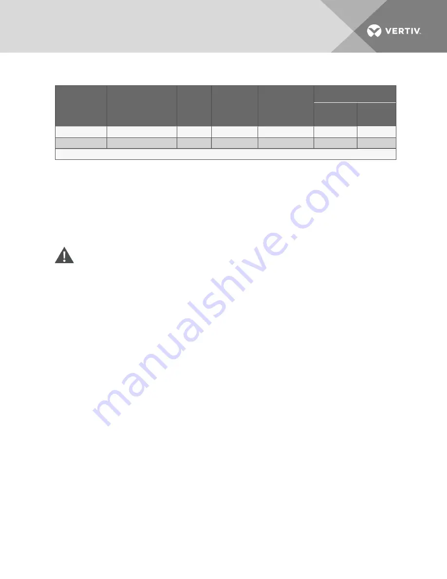
Drycooler Model
#
No. of Internal Coil
Circuits
No. of
Fans
Internal
Volume,
gal. (L)
No. of
Inlets/Outlets
Inlet & Outlet Connection Size
OD Copper,
in.
ID Sweat, in.
880
80*
8
44.0 (166.5)
4/4
—
2-1/8
940
96*
8
52.0 (196.8)
4/4
—
2-1/8
* = Standard Circuiting
Table 6.14 Standard drycooler piping connection sizes and internal volume
6.10 Mounting the Drycooler
The drycooler must be installed so that it is level within 1/2" (13mm) to ensure proper glycol flow, venting
and drainage. For roof installation, mount the drycooler on suitable curbs or other supports; follow all local
and national codes. Secure the legs to the mounting surface using a field-supplied 1/2" (13mm) diameter
bolt in each of the two 9/16" (14mm) holes in each leg. See Figure 6.13 on page 138 for anchor dimensions.
6.11 Glycol Piping
CAUTION: Risk of explosive discharge of high pressure gas and flying projectiles. Can cause
building and/or piping damage and personal injury.
Units are shipped from the factory with a pressurized dry nitrogen holding charge. Carefully
relieve the pressure before cutting into the piping system.
NOTICE
Risk of excessive coolant fluid pressure, improper piping material, and unsupported piping. Can cause
piping rupture, coolant fluid leaks and building and/or equipment damage.
To avoid the possibility of burst pipes, the system installer must supply and install a relief valve in the
system. Galvanized pipe must not be used in glycol systems. To help prevent piping failures, supply and
return lines must be supported such that their weight does not bear on the piping of the unit or pumps.
6.11.1 Piping Guidelines
Piping between the drycooler, the pump and the indoor unit is required to complete the system and is to
be provided and installed by the system installer. All fluid piping must comply with local codes. Properly
sized pipes will help reduce pumping power and operating costs.
Pipe material choices are typically copper, plastic or steel/black iron. Consult glycol and pipe
manufacturing literature for compatibility and sizing assistance. Galvanized piping should not be used.
Any copper piping installed should be “L” or “K” refrigerant grade copper.
See Figure 6.12 on page 136 for a typical piping diagram, depicting multiple indoor units, multiple
drycoolers and dual pumps. Single indoor unit/pump/drycooler systems are also possible.
Drycooler supply and return connections vary in size and number. Refer to Table 6.14 above. Vertiv
recommends installing manual service shutoff valves at the supply and return connections of each
drycooler and indoor cooling unit. The shutoff valves permit isolating equipment for routine maintenance
and for repairs.
Vertiv
| Liebert® Xtreme Density™ System Design Manual |
140
Summary of Contents for Liebert XD Series
Page 1: ...Liebert Xtreme Density System Design Manual...
Page 18: ...Vertiv Liebert Xtreme Density System Design Manual 18 This page intentionally left blank...
Page 20: ...Vertiv Liebert Xtreme Density System Design Manual 20 This page intentionally left blank...
Page 66: ...Figure 4 2 Overall dimensions Vertiv Liebert Xtreme Density System Design Manual 66...
Page 88: ...Figure 4 21 Liebert XDV dimensions Vertiv Liebert Xtreme Density System Design Manual 88...
Page 152: ...Vertiv Liebert Xtreme Density System Design Manual 152 This page intentionally left blank...
Page 166: ...Figure 7 7 Modules on a single chain Vertiv Liebert Xtreme Density System Design Manual 166...
Page 167: ...Figure 7 8 Modules on two chains Vertiv Liebert Xtreme Density System Design Manual 167...
Page 182: ...Vertiv Liebert Xtreme Density System Design Manual 182 This page intentionally left blank...
Page 199: ......


