User Manual 10H52258UM60 - Rev. 3 - 01/2019
22
APM 400/600
Electrical Installation & Connections
4
Electrical Installation & Connections
Once the mechanical installation procedures have been completed, it is necessary to carry out the electrical
installation procedure, which involves connecting the various electrical power and signal cables. The various
signal cables must be kept away from the power cables irrespective of whether they are shielded or insulated.
Warning
Do not attempt to switch the UPS on unless the authorized service engineer is present. The power cables must
be connected to the UPS by an authorized engineer taking into consideration the information contained in the
manual as well as all the labels on the unit.
4.1
Power Cable connections
This section explains the power cable connections in detail.
4.1.1
System Configuration
This section explains the system configuration of the 3 different cables, i.e., the UPS Input cable, he UPS Bypass
and Output cable, and the Battery cable.
UPS input cable
The UPS input cable cross section varies depending on the UPS power rating and the AC Input voltage. However,
the cable must meet the requirement of maximum input current, inclusive of the maximum battery charge current
(Refer to the Table 4.1).
UPS Bypass and Output cable
The UPS bypass and output cable cross sections vary depending on the UPS power ratings and output AC
voltages, subject to meeting the nominal output or bypass current requirements indicated in Table 4.1.
Battery Cable
Each UPS is connected to its respective battery via the positive terminal, negative terminal and neutral line. The
battery cable cross section varies depending on the UPS power ratings, subject to battery discharge current
requirement as it reaches the EOD voltage (Refer to Table 4.1)
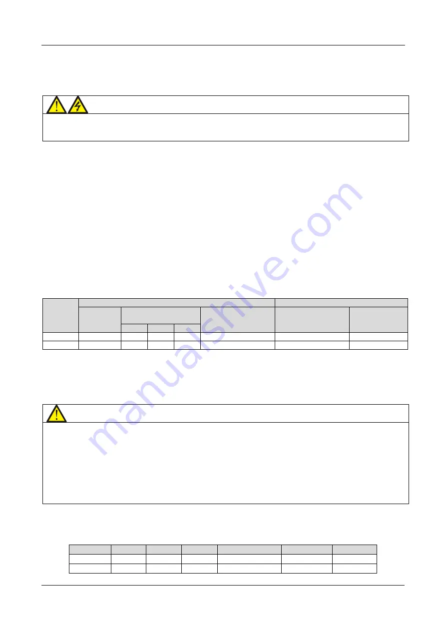
Table 4.1
4.1.2
Maximum Steady State AC and DC current
The battery cables must be selected based on the current and voltage indicated in Table 4.1. Adhere to the local
wiring regulations and take environmental conditions, such as temperature and other physical factors, in to
consideration. Refer to the table 3B in IEC 60950 -1.
Note
IEC/EN/CSA 60950-1 "Safety of information technology equipment" is one of the world's most widely-used
electrical product safety standards. This standard is applicable to mains powered or battery powered
information technology equipment, including electrical business equipment and associated equipment, with a
RATED VOLTAGE not exceeding 600 V. It is one of the relatively few standards to be harmonized by
standards-writing bodies globally to make the process as efficient as possible for manufacturers.
Maximum low voltage current for the rectifier load at full load.
Non-linear loads (such as Switch power) affect the design of the output and bypass neutral lines.
Discharge current at EOD point (voltage is 9.6 V) based on a 38-block battery.
4.1.3
Recommended CSA of Individual Module Cable
The recommended CSA of the individual module cables is indicated in Table 4.2 below.
Table 4.2
Model
Input
Output
Bypass
I/O neutral line
Earth cable
Battery
400 kVA
2 x 185
2 x 185
2 x 185
2 x 185
2 x 185
Table 7-4
600 kVA
3*185
3*185
3*185
3*185
2*185
Table 7.4
The Input, Output, Bypass, I/O neutral line, and Earth cable cross sections are all expressed in sq-mm.
UPS
power
(kVA)
Rated current (A)
Bus stud bolt/nut specification
Max. input
current
Output/bypass current
at full load
Battery discharge
current (+, -, N) at min.
battery voltage
Input, battery, output,
bypass/PE cable
Recommended
torque (N.m)
380V
400V
415V
400kVA
797
606
577
556
1153
M16/M12
90/40 (PE cable)
600kVA
1196
909
866
835
1730
M16/M12
90/40 (PE cable)


