47
User Manual 10H52258UM60 - Rev. 3 - 01/2019
Introducing UPS Operations
APM 400/600
6
An introduction to the UPS operating procedures
This section concentrates on the precautions and routine operating methods under day-to-day real-time
conditions. But before proceeding, a brief explanation of the Design concept (including System Design, Bypass,
and System Control Principle and Operation Modes) is provided in order to familiarize users with the inner
workings of the APM UPS.
Design Concept
This section provides a detailed description of the system design, Bypass, UPS Power Supply Switch
configuration, Battery Circuit Breaker (BCB), and System Control principle.
System Design
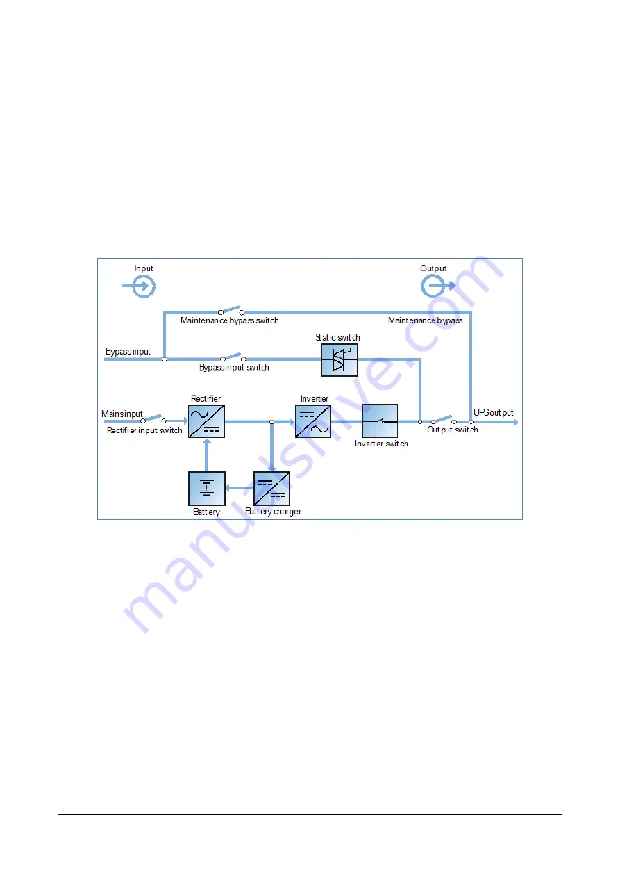
This section introduces the working principle of the UPS single module. The UPS is based on the AC-DC-AC
converter configuration (as shown in Figure 6-1). The first stage conversion (AC-DC) uses the three-phase, high
frequency rectifier to convert the three-phase mains input voltage into a stable DC bus voltage.
Figure 6-1 Block diagram illustrating the operating principle of UPS single module
The UPS includes a built-in battery charger and uses advanced temperature compensation technology to
effectively prolong the battery service life. The inverter employs large power IGBTs, as well as advanced SVPWM
control technology, to reconvert the DC bus voltage to AC voltage.
When the mains is within normal operating limits, the rectifier and inverter work together to supply the loads and
charge the battery.
When the mains is outside these limits, the rectifier stops working, and the battery supplies power to the loads
via the inverter. If the battery voltage reaches the End Of Discharge (EOD) voltage and the mains power supply
has still not been restored, the UPS will shut down (if the system uses split bypass configuration and the bypass
is normal, the system will transfer to bypass). The battery EOD voltage value is preset. When the mains is outside
the normal operating limits, the UPS continues to operate on battery power until the battery voltage reaches the
EOD voltage, whereupon the UPS shuts down; this period is known as the Backup Time. The duration of the
backup time depends on the battery capacity and size of the load.
Bypass
Thanks to the intelligent control exercised by the Static Switch module (as shown in Figure 6 -1), which contains
the controllable electronic switch, the loads may be supplied either by the inverter or the bypass. Under normal
operating conditions, the loads are supplied by the inverter, and the automatic inverter switch on the inverter
side is closed. In the even of an overload (the overload delay time expires) or inverter failure, the automatic
inverter switch is opened, and the Static Switch module transfers the loads to the bypass automatically.
In order to transfer the load between the inverter and bypass without interruption under normal operating
conditions, the inverter output must be synchronized with the bypass.


