User Manual 10H52258UM60 - Rev. 3 - 01/2019
72
APM 400/600
Parallel System and LBS System
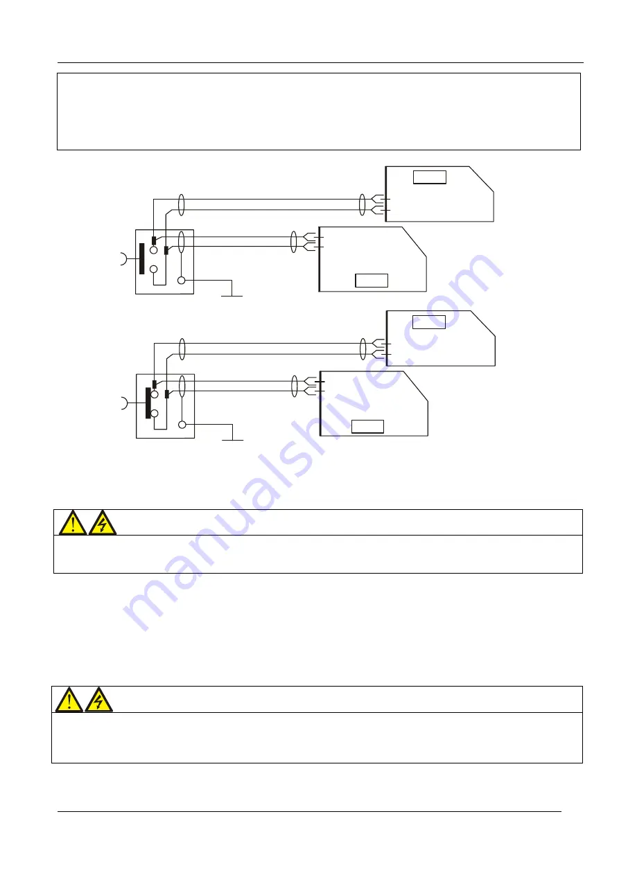
1. The remote EPO switch shall be realized by means of a normally open or normally closed dry contact.
2. The dry contact voltage and current ratings are 2 Vdc and 20 mA, respectively.
3. The external EPO device may consist of another control system, which can be used to disconnect the UPS mains
supply or bypass input.
4. A jumper is connected between pins 1 and 2 of the normally closed EPO-J2 port on the bypass module in the
factory.
J3 3.3
EPO
UPS1
EPO
UPS 2
UPS1
UPS 2
J3 3.4
J3 3.3
J3 3.4
J3 3.1
J3 3.2
J3 3.1
J3 3.2
board
Communication
Communication
board
Communication
board
Communication
board
UPS 2
J3 3.3
J3 3.4
Communication
board
J3 3.3
J3 3.4
Communication
board
UPS 1
UPS 2
J3 3.3
J3 3.4
Communication
board
UPS 1
J3 3.3
J3 3.4
Communication
board
EPO
EPO
J2
J2
2.3
2.4
Bypass module
J2
J2
2.3
2.4
Bypass module
J2
J2
2.1
2.2
Bypass module
J2
J2
2.1
2.2
Bypass module
Bypass control
module
Bypass control
module
Bypass control
module
Bypass control
module
Figure 8-4 EPO circuit diagram
N.B.: The Normally Open EPO circuit is shown at the top of Figure 8-4, whereas the Normally Closed version s
shown at the bottom.
8.3
Operation Procedures For Parallel Systems
Warning
If UPS input uses RCDs, the differential switch is only used in the system bypass mains supply. At the moment when
the electrical power supply is connected, the current may not be separated immediately, which may result in the
respective RCCB tripping.
This procedure should be carried out one step at a time, and each step must be completed on all the UPS
modules in the system before proceeding to the next step.
8.3.1
Startup Procedures In Normal Mode
These procedures are used to start the UPS when it is completely de-energized, which means that neither the
UPS nor the maintenance bypass switch have been used to supply the load yet. Make sure UPS has been
installed completely and commissioned by the engineer, and that the external power supply switch is in the OFF
position.
Warning
1. These procedures result in mains voltage being applied to the UPS output terminals.
2. If any load equipment is connected to the UPS output terminals, check with the user that it is safe to apply power. If
the load is not ready to receive power, disconnect the downstream load switch, and apply a warning label on the load
connection point.
To switch the UPS on from the fully de-energized condition, proceed as follows:


