Marquee ACON Ultra Installation/Operation Guide
1-11
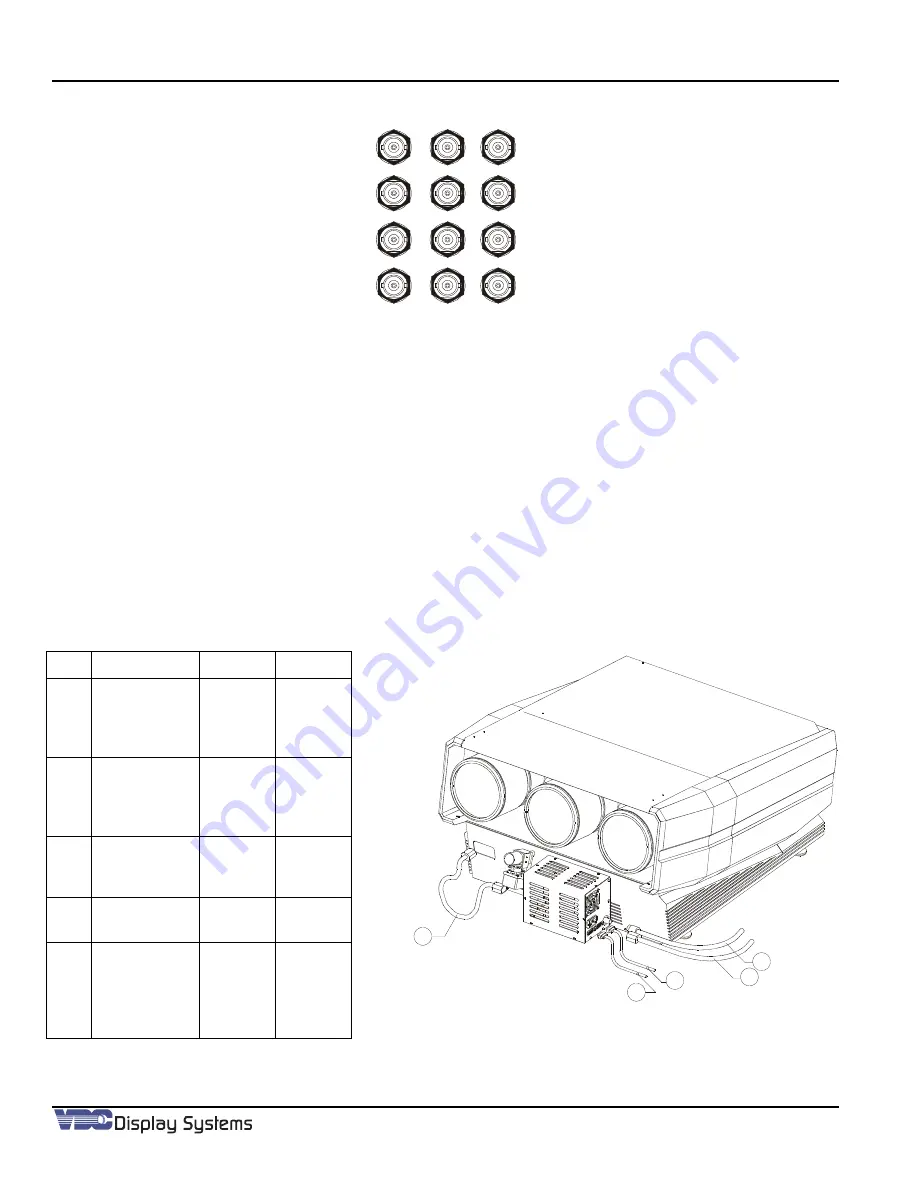
Figure 1-10. Video Boards Inputs. Video ID (Board, Channel)
Figure 1-12 illustrates a 9-projector installation. The projector IDs’ are 1 through 9. The RS232 Serial port 1 from the
AU
Server is routed to Projector 001 (1). The RS232 loop-thru on Projector 1 is then routed to Projector 002 (2) then
looped to Projector 003 (3). This continues for the next 2-groups (3-each projector) in the installation using
AU
Server
serial ports 2 and 3. Port 3 is by way of the
AU
Server expansion port and cable adaptor P/N 81749-02.
The camera(s) communications is similar to that of the projector(s) communications. Whereas, RS232 port 4 in
Figure 1-12 is connected to Camera ID 1, then looped to Camera ID 2, and then looped to Camera ID 3. Then RS232
port 5 to Camera ID 4, looped to Camera ID 5 looped to Camera ID 6. Leaving RS232 serial port 6 connected to
Camera ID 7, looped to Camera ID 8, looped to Camera ID 9.
1.4.4.1
Camera AC power Configuration:
Main AC power is supplied to each camera assembly mounted on a projector, either on the front panel or top bracket.
Then the AC “out” from each camera is applied to the relevant projector using the 3’ Jumper AC Cord (Supplied).
Item
P/N
From
To
1
66650-01
ACON
Ultra
Camera
AC “Out”
Projector
AC “In”
2
34-001306-
02
Camera
RS232
“Out”
Next
Camera
RS232
“In”
3
34-001306-
02
ACON
Ultra
Server
Camera
RS232
“In”
4
N/A
Main
Supply
Camera
AC ‘In”
5
66649-01
Camera
Video
“Out”
ACON
Ultra
Server
Video
Matrix
Figure 1-11. Camera/Projector Connections
1
2
3
4
5
Summary of Contents for MARQUEE ACON Ultra Camera Kit
Page 2: ...VDCDS Doc 79024 01 Revision 2 0 2 07 30 2007 MARQUEE ACON Ultra Operation Maintenance Manual ...
Page 3: ......
Page 4: ......
Page 5: ......
Page 19: ......
Page 31: ...Marquee ACON Ultra Installation Operation Guide 2 8 AU User Controls Settings and Operation ...
Page 67: ......
Page 75: ......


