28 MOUNTING OF SWITCHES
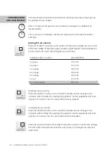
CONNECTION OF BUILDING MANAGEMENT SYSTEM:
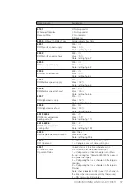
1-10V CONTROL SIGNAL
With 1-10V the flow can be set steplessly between the minimum and maxi-
mum flow of the ventilation unit. This corresponds to the following values:
1 V
25 m³/h
1 – 10V
Linear connection
10 V
225 m³/h *
*the indicated air flows are in function of and dependent on the total pressure loss of the ventilation
system to be overcome.
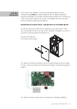
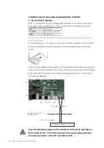
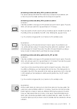
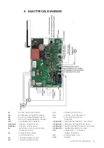
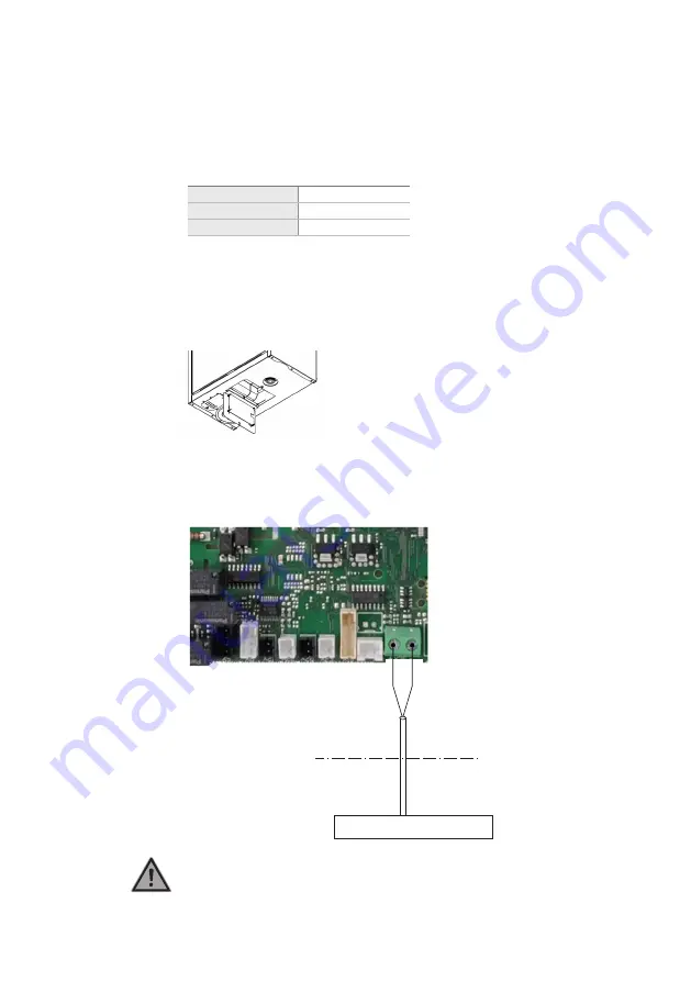
For connecting a 1-10V signal, on the bottom of the ventilation unit the circuit
board compartment must be opened so as to be able to reach the circuit
board:
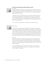
Then a correct cable must be guided to the circuit board via the grommet pro-
vided for this in the ventilation unit. As the last step, connect the control signal
to terminal X26 “Connection of building management system”, according to
the following diagram.
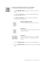
Then the Automatic position of the ventilation unit must be activated so
that it reacts to the 1-10V control signal. For this press during at least 3
seconds on position 1 of the RF 3-position switch.
X9
X8
X6
X22 X23
X5
X21 X20
X15
X26
Provided grommet in
ventilation unit.
2 x 1,5 mm
2
(maximum)
Building management system
1-10V signal Ground

