background image

---92---

I. Checks and adjustments

I 5.1.2.

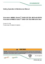
Adjusting toe ---in 4WD

A3565--- 139

1

2

Slacken the locking screw (

1

) of the tie rod and turn the

adjusting screw (

2

) in the desired direction. Tighten the

locking screw.

Adjust both tie---rods so that there is no restriction of the
steering lock. Check toe---in as before.

I 5.2.

Limiting steering lock of front

wheels

(powered front axle)

A3565--- 140

1

2

CAUTION: When altering the track width or when
fitting a front loader, always make sure that the front
wheels have free movement to full lock in both
directions and that the front axle and the wheels can
turn fully.

If necessary adjust the steering lock stops on

the powered front axle.
To carry out the adjustment slacken the locking nuts (

1

)

and adjust the adjusting screws (

2

). After adjusting tighten

the locking nuts.

NOTE: Adjust the adjusting screws of both sides to the
same length, so that the turning angle is the same on
both sides.

I 6.

Adjusting track width

When track widths are adjusted or larger tyres/tires
fitted, the turning angles have to be checked/adjusted
for max turning angle of the front axle on both sides.
Check also when using chains that the distance from

the cab to the tyres/tires does not go below 80 mm.
Check that the distance from parking lights to the
outer sides of the tyres/tires does not exceed 400 mm.

I 6.1.

Front axle

Apply the parking brake or scotch the rear wheels to
ensure the tractor cannot move.

Summary of Contents for 600

Page 1: ...Operator s manual 600 900...

Page 2: ...69 1 6 1 Operator s manual 600 900 Serial numbers of your tractor Engine number Tractor number Type plate on some marketing areas Type plate EEC Cab number Powered front axle number...

Page 3: ...on section of the instruments and controls part etc The detailed table of contents provides a lettering a numbering and page system The bottom of each page displays a reference to the main part of the...

Page 4: ...not easily be fitted at a later time to the tractor Extra equipment means the equipment which can be bought and mounted at a later time to the tractor We recommend that you read the manual thoroughly...

Page 5: ...E 5 Action to be taken during using 51 E 5 1 Permitted driving inclinations for a tractor on a slope 51 E 5 2 Use of snow chains 51 E 5 3 Towing the tractor 51 F Operating instructions 52 F 1 Use of p...

Page 6: ...07 J 11 1 The capacity of the cab filter 107 J 11 2 Code number table for calibrating 107 J 12 Wiring diagram component list 108 J 13 Wiring diagram 110 K Extra equipment 113 K 1 Extra equipment catal...

Page 7: ...slippery ground as then the front wheels are braking 2 Children and tractor Never allow children in the cab or near the tractor or attached implement while the engine is running Always lower the imple...

Page 8: ...suitably marked During day time this is done with a flag and during darkness with a red light and reflector arrangement 16 Trailer A trailer should only be coupled to the drawbar A loaded drawbar must...

Page 9: ...arking brake is applied or the wheels blocked in order to prevent the tractor from moving 23 Damage The driver is responsible for seeing to the repair of any wear which might endanger the safety of th...

Page 10: ...By a fire At temperatures in excess of 300 C e g if the engine is on fire the viton seals of the engine e g the undermost 0 ring of the oil pressure regulating value produce very highly corrosive hyd...

Page 11: ...N NOTE or INSTRUCTION stickers are missing they have to be ordered according to the spare parts catalogue and re affixed immediately in their places 3 3 2 4 1 2 1 1 Electrohydraulically controlled hyd...

Page 12: ...11 B Safety precautions 1 2 1 HiShift is optional equipment 2 Electrohydraulically controlled hydraulic lift...

Page 13: ...the front shield are the normal headlights The lower lights on the cab are parking lights The outer upper lights on the cab are the upper headlights They are optional equipment They are not fitted in...

Page 14: ...13 B Safety precautions Rear lights The lower lights are parking lights The upper lights are working lights They are as optional equipment...

Page 15: ...r take off On these models an engine heater is included as standard The tractor is obtainable with powered front axle and as alternative equipment a forestry cab and either an additional low gear or o...

Page 16: ...mostat housing 3 Alternator 4 Hydraulic pump 5 Suction strainer hydraulic system 6 Starter motor 7 Fuel filling opening 8 Hand priming pump fuel system on distributor pump models on in line pump model...

Page 17: ...g gear 7 Lifting link trailer hitch extra equipment with the hydraulic hitch 8 Extra lifting cylinder 9 Top link 10 Incorporating breather hydraulic system 11 Oil filling hydraulic system 12 Dipstick...

Page 18: ...ngines of the 420 series The tractors have 4 stroke direct injection diesel engines Three cylinder engine normally aspirated 600 Three cylinder engine turbocharged 700 Four cylinder engine turbocharge...

Page 19: ...oil filter C 4 3 Rear axle The rear axle is fitted directly to the gearbox The differential lock is of the pawl type which is engaged and disengaged by means of a spring loaded lever An indicator lam...

Page 20: ...h multi disc brakes are located between the differential and final drive gears in the final drive housing The brakes operate hydraulically from the brake pedals The pedals can be connected together an...

Page 21: ...B ACB is fitted the control levers are replaced with knobs and switches Pre programmed programed functions Draft control position control combining ratio plus sensitivity on the regulator the sensitiv...

Page 22: ...ection K after each extra equipment D 1 Illustrations NOTE The places of the switches can vary depending on the equipment D 1 1 Controls on front 69 9 1 2 3 4 1 5 For more detail see page 28 1 Clutch...

Page 23: ...ft the Agroline instrument panel is standard 2 1 Fuel gauge 2 2 Tachometer 2 3 Coolant thermometer 2 4 Indicator lights for direction indicator 2 5 Indicator light for main beam 2 6 Indicator lights o...

Page 24: ...Locking device of position control lever 2 3 Lowering speed control Rear power take off 3 for more detail see page 38 3 1 Selector lever power take off Auxiliary hydraulic 4 for more detail see page 3...

Page 25: ...knob forced lowering switch 1 11 Inner switch for connecting implement corresponding push buttons are located on both mudguards Side pillar control panel 2 for more detail see page 42 The places of t...

Page 26: ...These fastening points are located below the covering panel middle screw in the same line with the panel fixing screws and are 100 mm from each others To make the fastening holes accessible carefully...

Page 27: ...console 69 1 5 5 2 4 6 6a 7 3 1 For more detailed see beginning page 45 1 Recirculation control knob extra equipment with air conditioning 2 Roof heater fan 3 speeds extra equipment 3 Air conditioning...

Page 28: ...s seat 3 1 2A 4 5 2 6 6 69 33 For more detailed see beginning page 46 1 Adjustment forward rearward 2 Suspension 2A Weight decal 3 Lock for turning seat 4 Seat belt anchor point 5 Seat back inclinati...

Page 29: ...this lever the indicator light lights up on the instrument panel move the lever 2 backwards to the locked position 65 15 A select the desired PTO range speed with the power take off selector lever A m...

Page 30: ...the hydraulic pump should fail for any reason the tractor can still be steered manually with the steering wheel At full lock it is possible to force the steering wheel further manually This slip of th...

Page 31: ...ndscreen wiper and washer 1 6 The switch controls both the windscreen washer and wiper D 2 2 1 7 Ventilation nozzles 1 7 Turn the nozzles to direct the flow of air The corresponding nozzles are also o...

Page 32: ...an be moved to the roadside 8 Not in use 9 Not in use 10 Not in use 11 Not in use 12 Not in use 13 Thermostart glow yellow is on when the starter switch is in the glow position 14 Rear power take off...

Page 33: ...ttom line When the tractor starts to move the bottom line display changes to show the driving speed 2 Displays chosen with change over switch 2 8 1 for LCD display in Agroline instrument panel The top...

Page 34: ...he ignition on The tool symbol will illuminate again when the next service interval has been reached When the power is switched on the last display is shown in the display unit 2 3 Resetting driving t...

Page 35: ...ges from a smaller value to greater one The code numbers and corresponding tyres tires are listed in the table on the page 107 D 2 2 2 9 Change over switch for LCD display unit in Agroline instrument...

Page 36: ...range L range Rear position on right in the driving direction reverse R range Rear position on left in the driving direction high range H range D 2 3 1 2 Speed gear lever 1 2 69 26 85 1 1 1 3 1 2 This...

Page 37: ...ns such as attaching the implements a1 Operating and function of the HiShift 69 26 6 1 4 1 4 1 4 By pressing this push button 1 4 the clutch pedal is depressed When the push button is released the clu...

Page 38: ...released the clutch pedal rises quickly to the point when the clutch begins to engage knee point this point has been preset in the factory 4 If the speed is below 4 km h then the pedal rises slowly lo...

Page 39: ...fferential lock can be engaged while running straight ahead without wheel slip D 2 3 2 Rear linkage mechanically controlled hydraulic lift 2 D 2 3 2 1 Position control lever 2 1 2 1 2 2 69 27 5 Front...

Page 40: ...ion coupling by left right movement When the lever is pulled back or to the left pressure acts in the upper quick action couplings of the double quick action couplings e g tipper control and vice vers...

Page 41: ...n must only be carried out when the main power has been switched off and when the inner switch for connecting implements or the push button control has been used The flashing of the diagnostic light i...

Page 42: ...lowering movement of the lower links press the lift or lower button D 2 4 1 7 Draft control selector 1 7 1 4 1 5 1 6 1 7 1 8 1 4 1 9 69 31 1 This knob should be turned to the P position when the posit...

Page 43: ...sition control system must be activated by operation of the lift stop lower switch 1 3 CAUTION The transport height selector 1 6 does not limit the lifting height when these switch buttons are being u...

Page 44: ...ctric main circuit switch are under Extra equipment in section K on page 115 D 2 4 3 Other controls 3 D 2 4 3 1 3 pin power socket 3 1 2 1 3 1 69 31 5 The socket 3 1 is of the 3 pin type ISO TR 12369...

Page 45: ...parking brake when the tractor engine is running brake pedals have to be connected together When the tractor engine is off and the parking brake is on the trailer brakes do not operate D 2 5 2 Engagi...

Page 46: ...this position The windows will demist faster reduces humidity ice forming The pressure in the cab will be higher reduces dust quantity D 2 7 2 Roof fan 2 3 speeds extra equipment This fan blows air t...

Page 47: ...t can be lowered and by pulling the string 6a the sun visor can be raised D 2 7 7 Radio 7 extra equipment D 2 8 Seat 2 1 3 3A 5 4 6 69 34 CAUTION Do not attempt to adjust the seat while driving increa...

Page 48: ...8 4 Seat belt anchor point 4 There are anchor points for the seat belt on the seat D 2 8 5 Seat back inclination 5 Pull this lever up then set the back rest to the desired position D 2 8 6 Vertical ad...

Page 49: ...on therm and start positions 1 Depress the clutch pedal and move the gear lever to the neutral position 2 Move the hand throttle lever to the low idling position 3 Turn the starter switch key to the T...

Page 50: ...re Never try to start the engine by short circuiting leads Having started the engine declutch select the correct gear and release the parking brake Steadily increase the engine speed and release the c...

Page 51: ...se the desired driving direction with the RH side lever When starting forward it can be chosen high H or low L range Changing from High to Low while the tractor is moving is not recommended the differ...

Page 52: ...Sideways to the right 600 700 32q 800 900 28q Sideways to the left 600 700 40q 800 900 28q Combined to the sides lengthwise 600 700 25q 20q 800 900 25q 20q WARNING Angles for safe driving should be s...

Page 53: ...n Adjust engine revs NOTE When using the 540 E position be aware that when increasing the engine revs the PTO shaft can rotate up to 800 r min F 1 2 Disengagement In reverse order The power take off i...

Page 54: ...yre tire pressures and permissible loadings are given in the Technical specifications see page 98 and the trailer hitch loading in the Extra equipment see page 127 If the tractor is fitted with an opt...

Page 55: ...ews must be lowered back down to the locked position A3565 65 3 1 The lifting links can be attached to the lower links at one of two holes Different holes give different lifting ranges and lifting pow...

Page 56: ...d with the cotters F 4 1 1 Position lever 3 1 65 42 1 Move the lever 3 backwards to raise the lower links and forwards to lower them When the position lever is set in an intermediate position the lowe...

Page 57: ...the top link 4 on the tractor Draft control sensitivity is least when the top link is connected to the lower hole and greatest when connected to the upper hole Draft control is used when working with...

Page 58: ...wer links are raised when the position control knob 1 is turned clockwise and lowered when it is turned anti clockwise When the knob is set to an intermediate position the lower links take up and main...

Page 59: ...position When the draft resistance exerted by the implement on the lower links rises to the value set the linkage lifts the implement in order to counteract the increase in resistance trying to keep i...

Page 60: ...d CAUTION Take great care if using unfamiliar trailers or implements as the oil in the cylinder can contaminate the oil in the hydraulic system of the tractor If the external hydraulics are used exten...

Page 61: ...disengaging implements When engaging or disengaging implements with push buttons always stand outside the implement and beside the tractor Never stand on the implement or between the implement and th...

Page 62: ...5 52 2 The hydraulic lift has a greater lifting force when the top link is moved upwards on the tractor and downwards on the implement 65 53 3 Top link set too long giving poor lifting height on rear...

Page 63: ...o avoid the risk of fire The fuel lubricating oil and coolant cause irritation to skin if in contact for long periods After completion of any service work replace all safety covers etc G 1 2 Lubricati...

Page 64: ...water standardi ASTM D3306 86a or BS 6580 1985 13 5 800 6580 1985 15 5 900 15 5 Brake fluid reservoir Brake fluid SAE J1703 0 3 Windscreen washer Washer fluid 1 5 Bio oil is also possible on hydraulic...

Page 65: ...e pilot pressure drops too low engine power is reduced smoke increased and starting becomes more difficult Additionally water in the injec tion system will destroy it in a very short time For this rea...

Page 66: ...ing links 70 6 Check fluid level in windscreen washer 70 7 Check belt tightness 70 8 Check electrolyte level in battery 70 9 Check prefilter on distributor pump models and fuel filter of fuel system 7...

Page 67: ...78 32 Change air filter and safety filter 79 33 Lubricate front wheel bearings 2 wheel drive 79 34 Check and adjust toe in front wheels 2 nipples 80 35 Adjust valves 80 36 Change cab air filter and up...

Page 68: ...ight illuminates quickly in dusty conditions check the ejector pipe 1 is fitted properly 800 900 the models 600 and 700 have dustvalves Cleaning Always stop the engine before cleaning A blockage of th...

Page 69: ...lowing order 4 1 3 2 69 60 2 ALWAYS open the cap 3 of the expansion tank 2 first Open the expansion tank cap carefully When running the tractor the expansion tank has overpressure 0 7 bar After that o...

Page 70: ...ke the weight off the axle B Steering knuckles Turn the steering wheel backwards and forwards when lubricating 2 pcs 4 wheel drive models A3565 88 1 A A A Front axle mountings Lubricate the nipples wi...

Page 71: ...hen it can be pressed in about 20 mm 0 79 in with the thumb halfway between the belt pulleys Remove the finger shield if necessary Tensioning fan belt Loosen the alternator attaching bolts Turn the al...

Page 72: ...le while after topping up with distilled water otherwise the water can freeze before it has mixed properly with the battery acid WARNING Be carefully with the battery solution danger from corrosion H...

Page 73: ...remove chemicals from the outside air Clean upper filter extra equipment 69 66 Remove the air cleaner housing from the front part of the roof and service as for the lower filter H 4 2 Change engine oi...

Page 74: ...nded that the changing of tyres tires and wheels is carried out in a professional tyre tire workshop which is equiped to handle this type of work DANGER When welding the discs the tyre tire must be aw...

Page 75: ...n page 90 H 5 1 1 Adjusting parking brake 65 73 The parking brake acts on the foot brake mechanism mechanically by means of a rod Adjust the free travel if necessary see under Checks and Adjustments o...

Page 76: ...oil level in hub reduction gears powered front axle 21 A3565 108 Turn the wheel until the oil surface indicator line is horizontal The oil surface should be level with the hole Add more oil if necessa...

Page 77: ...On tractors with a return filter all oil which is returning from the outside machine goes through the return filter Follow to changing intermediate on the return filter H 5 9 Change oil filter in tra...

Page 78: ...iner Clean the plugs and screw them in again Filling 65 75 Oil quality should be in accordance with the table on page 63 Remove the plug on the dipstick opening Fill up with new oil to the upper mark...

Page 79: ...er seal is leaking and must be changed or retightened H 6 6 Clean fuel tank 30 Always clean the fuel tank at the start of the winter season This avoids problems with condensation in the fuel tank Alwa...

Page 80: ...tion Check that the sealing surfaces are clean Fit a new safety filter and make sure that it is correctly positioned in the housing Tighten the nut 1 carefully Fit the main filter carefully Tighten th...

Page 81: ...adjusted when the engine is either warm or cold Checking and adjustment should be carried out by an authorized workshop H 6 12 Change cab air filter and upper filter extra equipment 36 Change lower fi...

Page 82: ...means of compressed air or by flushing through with water Also clean from the fan side of the radiator The cooling system can be thoroughly cleaned if problems occur in the function in which case cle...

Page 83: ...tank s cap has to be open when filling Fill the expansion tank 2 with fluid up to the fluid level sign 3 NOTE If the finger shield is removed make sure you re fit it H 7 1 3 Coolant volume 600 13 5 l...

Page 84: ...brake fluid reservoir open the bleed nipples It is better to place hoses from the nipples into a con tainer as the fluid corrodes the paint Pump the brake pedal until all brake fluid in the pipes and...

Page 85: ...are changed according to schedule and that the fuel system is kept clean Note particularly that the air filter must be clean and have good flow through properties Regularly check the attachment of the...

Page 86: ...lever 1 on the fuel pump If pumping feels ineffective turn the engine a little so the camshaft turns away from the line of the pump arm 69 89 3 2 2 Open the bleed screw 2 Operate the hand pump 1 until...

Page 87: ...ole 2 on the cover Open the glow plug pipe adapter 3 I 1 2 Air cleaner 69 90 The air cleaner prevents dust and other dirt from entering the engine with the induction air Engine wear is largely depende...

Page 88: ...system A3565 129 The following action should be taken to make sure that the cooling system functions correctly Check the coolant level see maintenance program daily checks Check the fan belt tension...

Page 89: ...rging circuit must not be broken when the engine is running I 2 3 Safety precautions for the electrical system Always connect the battery with the correct polarity Disconnect the negative lead of the...

Page 90: ...dge of the light pattern should come at height H when the tractor is at distance L With full beam switched on the distance between the light points should be B Any necessary adjustment is done by usin...

Page 91: ...he wheels can rotate freely Check by driving with the pedals connected together that the brakes do not pull to one side Check the pedals free travel I 4 2 Adjusting parking brake The parking brake is...

Page 92: ...wer down the fluid brakes of the trailer see the bleeding instructi ons on page 123 the air pressure brakes see the bleeding instructions on page 121 I 5 Steering system I 5 1 Checking and adjusting t...

Page 93: ...djust the steering lock stops on the powered front axle To carry out the adjustment slacken the locking nuts 1 and adjust the adjusting screws 2 After adjusting tighten the locking nuts NOTE Adjust th...

Page 94: ...5 1405 1495 1665 1755 The standard track widths are underlined Adjusting front and rear wheel track widths is done in the same way Track width can be adjusted by changing the position of the wheel rim...

Page 95: ...ditioning is operated for a few minutes at least once a month For a period longer than two months Clean wash and lubricate the tractor Clean the fuel tank Fill the fuel tank with fuel Change prefilter...

Page 96: ...nd backwards so that the sealing ring of the coolant pump works loose it may have stuck to the shaft Wash off any anti corrosion oil applied to the exterior of the tractor Tension the fan belt compres...

Page 97: ...rawbar varies depending on equipments weights are determined according the EU directives Tractor 600 2 700 2 800 2 900 2 Rear front tyres tires 16 9R34 10 00 16 16 9R34 10 00 16 18 4R34 10 00 16 18 4R...

Page 98: ...6 12 4R24 x x 13 6 36 12 4 24 x x 13 6R38 13 6R24 x 1 x 13 6 38 8 13 6 24 8 x x 14 9R38 12 4R28 x 230 95R48 230 95R32 x x 13 6R24 12IND 275 80R18 x x x 16 9R34IND 13 6R24 IND x x x 18 4R34 IND 14 9R24...

Page 99: ...40 65R34 160 2900 420 70R24 160 1900 540 65R34 60 1580 420 70R24 60 1070 13 6R36 8 160 1750 440 65R24 160 1800 13 6 36 6 160 1615 440 65R24 60 990 13 6 38 8 200 1950 12 4R28 160 1450 13 6R38 8 160 180...

Page 100: ...ot in forest cab In the cabin the distance between the mudguards is 924 mm In Forest model the left mudguard is 50 mm wider NOTE Standard track widths are underlined When track widths are adjusted or...

Page 101: ...tart pre heating of induction air Air cleaner dry paper element with blockage indicator Safety filter dry paper element Pre separator system 600 700 Cyclone cleaner 800 900 Ejector Capacity fuel tank...

Page 102: ...ted by lever No of speeds 12 12 With overdrive Speed ranges reverse gear operated by the same lever 2 ranges H high range synchronized L low range synchronized Overdrive synchronized opearted by own l...

Page 103: ...6 4 5 4 7 4 8 4 8 5 0 5 0 L2 OR L2 4 2 5 3 5 2 5 4 5 6 5 6 5 7 5 7 OR L2 L3 5 7 7 3 7 1 7 4 7 6 7 6 7 8 7 9 L3 OR L3 6 5 8 4 8 2 8 5 8 8 8 8 9 0 9 1 OR L3 L4 7 5 9 7 9 4 9 8 10 1 10 1 10 4 10 4 L4 OR...

Page 104: ...for small medium and large tyres tires the dynamic rolling radius is in brackets The values for other tyres tires can be found by comparing with those in the table 1 Forward reverse models 16 9 30 16...

Page 105: ...0 2074 L 1 2 3 2 7 3 0 OR L 1 2 7 3 1 3 5 L 2 3 2 3 8 4 1 OR L 2 3 6 4 3 4 7 L 3 5 0 5 9 6 5 OR L 3 5 7 6 8 7 5 L 4 6 6 7 8 8 6 OR L 4 7 6 9 0 9 9 H 1 8 0 9 5 10 4 OR H 1 9 2 10 9 12 0 H 2 11 0 13 0 1...

Page 106: ...min 37 5 46 5 51 5 58 J 7 5 Powered front axle Differential brake automatic differential brake Overall reduction 15 76 Ratio front axle rear axle 1 342 Oil volume in differential 6 5 l Oil volume in...

Page 107: ...laceable paper filter Suction filter washable metal gauze filter Available volume of oil for auxiliary hydraulics 24 or 14 l depends on filling quantity Continuous pressure e g hydraulic motor operati...

Page 108: ...heel Code num bers Rear wheel Code num bers 12 4R36 148 18 4 34 136 13 6 36 147 18 4R30 142 13 6 38 140 18 4R34 132 13 6R24 186 18 4R38 124 13 6R36 145 20 8R38 119 13 6R38 140 230 95R48 130 14 9 30 15...

Page 109: ...iShift radio 62 63 FD4 25A Current socket 64 FD5 5A Radio clock light alarm buzzer 1 In engine room F51 15A Electrically controlled main circuit breaker 70 Sym Code bol Component no G1 Battery 1 G2 Al...

Page 110: ...ion white X27 26 pins instrumentation blue X42 4 pins front PTO supply 22 X44 1 pin control stop optional equipment 59 X49 2 pins air suspension seat 32 X50 3 pin current socket 64 X51 1 pin rear buzz...

Page 111: ...110 J Specifications J 13 Wiring diagram component list on pages 108 109 33202000O 69 1 69 2...

Page 112: ...111 J Specifications Wiring diagram component list on pages 108 109 69 3 69 4...

Page 113: ...112 J Specifications Wiring diagram component list on pages 108 109 69 5...

Page 114: ...Shift PTO switch only with 55 l min hydraulic pump not together with air pressure instruments HiShift drive clutch PTO switch only with 55 l min hydraulic pump included Agroline instrumentation not to...

Page 115: ...America Hydraulic trailer hitch agricultural towing device North America K 1 8 2 Extra valve blocks When ordering the extra valve blocks you have to know if it is third or fourth valve block Auxiliary...

Page 116: ...s extra control stop possibility can be used e g on portable sawmill potato harvester etc machine use NOTE The safety stop is useful when the tractor is driving an implement and there is no control fr...

Page 117: ...4 CAUTION The front PTO shaft nominal rotating speed is 1000 r min and the rotating direction is to the left viewed from front Check that the implement is compatible before connecting The front PTO sh...

Page 118: ...filling the tractor has to be levell Oil quality 10W 30 API CE SF API GL 5 4 CCMC D4 2 Check the condition of the rubber joint 2 after 500 hours use check it has no wears breaks leaks Change when need...

Page 119: ...engine speed to low idling Press the opposite side to the symbols of the HiShift 1 down to disconnect the clutch disc OFF position the light on the instrumentpanel is on Move the PTO selector lever 3...

Page 120: ...itch By rotating the adjusting knob 3 the engagement speed of the PTO will be adjusted the lock nut A has to be slackened The basic settings are 3 5 turns open the adjustment range is between 1 turns...

Page 121: ...ng valve for trailer 7A Bleeding valves 8 Steering valve for trailer one pipe system 9 Two pipe system container line red 10 One pipe system connector black 11 Two pipe system brake line yellow 12 Bra...

Page 122: ...7 both brake pedal circuits have their own bleed nipples The control valve 7 is situated on the left side under the cab on the rearside of the pressure tank The control valve is situated lower than t...

Page 123: ...sure for the brake valve 6 Brake valve 6A Bleed nipple of the brake valve 7 Quick action coupling for the trailer brake 8 Hydraulic pump 9 Brake cylinders for the trailer 10 Auxiliary hydraulic valves...

Page 124: ...the brake valve 6 The release valve 4 and brake valve 6 are situated on the right hand side under the cab The release and bra ke valves are situated lower down than the brake cylinder of the tractor T...

Page 125: ...clockwise 30q e g can be used when ploughing plowing CAUTION If the seat has been adjusted further back than the lock limits the seat can touch the cab side trim when turning 1 3 Forward rearward adju...

Page 126: ...set the back rest to the desired position 1 8 Arm rest adjustment 8 Adjust the arm rest by removing the cover and changing the arm rest place in the mounting slot 1 9 Lumber support adjustment 9 By t...

Page 127: ...116 The condenser must be cleaned at regular intervals to remove dust insects and other particle Make cleaning easier by moving the condenser sideways as in picture WARNING Avoid contact with the ref...

Page 128: ...6 1 3 The trailer hitch is raised and lowered with the hydraulic lift control lever 1 It locks automatically in the raised position On tractors with an electro hydraulic lift the inner switch 2 is use...

Page 129: ...tion Check the adjustment by moving the lifting link by hand Adjustment is correct when the link moves loosely Adjust if necessary by turning the cotter at the upper end of the links until a suitable...

Page 130: ...tch Both the models have almost the same properties Also both models are suitable for North America 1 Specifications 69 132 Distance between hitch point and power take off and corresponding permissibl...

Page 131: ...ight of the mechanical and automatic jaws happens in the same way The height of the jaw can be changed by first pulling lever 1 upwards and then by turning it to left Move the jaw into the desired hei...

Page 132: ...pin is locked in the down position when the security knob is out When coupling the trailer the drawbar locking pin must be secured 69 124 To ensure the allowed pulling angles drawbar eyes with pullin...

Page 133: ...le total weight for the tractor is 55 kN 5500 kg with all jaws Max permissible vertical loading for the trailer hitch 12 5 kN 1250 kg with all jaws Automatic drawbar main pin diameter 31 mm 38 mm Mech...

Page 134: ...with an implement on the front linkage covering the headlights the upper headlights optional equipment have to be switched on WARNING When you drive on public roads and there is no implement on the fr...

Page 135: ...y hydraulic 39 Controls on RH side driving 35 Controls on RH side driving rear linkage electrohydraulically controlled lift 40 Controls on RH side rear linkage mechanically controlled hydraulic lift 3...

Page 136: ...controlled lift 55 Power take off 103 Power take off presentation 19 Power take off use 52 Power transmission 89 101 Power transmission oil changing 77 Power transmission presentation 17 Powered fron...

Page 137: ...136 L Alphabetical index W Wagon towing device extra equipment 130 Wiring diagram 110 Wiring diagram component list 108 Working hydraulics 106...

Page 138: ...llon U K 0 0275 bushel U K 0 110 peck U K 33 81 fluid ounces U S 2 1134 pints U S 1 0567 quarts U S 0 2642 gallon U S 0 0284 bushel U S 0 1135 peck U S 0 908 dry quart U S 1 kiloliter 219 97 gallons U...

Page 139: ...eights and volumes are based on pure water at 4 C under 760 mm of atmospheric pressure For additional conversion factors or for greater accuracy refer to National Bureau of Standards Misc Publ 233 or...

Page 140: ...arts U S 1 1012 liters Weight 1 ounce avdp 28 50 grams 1 pound 453 592 grams 0 4536 kilogram 1 ton short 0 907 ton metric 1 ton long 1 016 ton metric 1016 05 kilograms Volume per unit area 1 gallon U...

Page 141: ...wheel nuts front wheels 2WD models 130 Nm front wheels 4WD models 300 Nm rear wheels 550 Nm Rim wheel disc 310 Nm Tyre pressure recommendations Rear wheels Pressure kPa Front wheels Pressure kPa 16 9...

Page 142: ...Ref no 39 179 21 9 11 2002 Printed in Finland by Kopijyv English...

Reviews: