- 20 -
Water Connections
Water Connections at the Heat Pump
Quick Connect fittings are recommended to be installed on the water inlet and outlet connections.
It is recommended to use stainless steel or PPR pipes for the heat pump plumbing. The water inlet
and outlet connection to the heat pump accepts stainless steel or PPR pipe fittings.
CAUTION
—
Make sure that flow requirements and tap water turnover rates can be
maintained with the installation of additional heat pumps and plumbing restrictions.
Plumbing Installation Requirements
1. When water pressure exceeds 490Kpa, please use reducing valve to reduce the water
pressure below 294Kpa.
2. Each part connected to unit needs to be connected with method of loose joint and installed with
intermediate valve.
3. Ensure that all plumbing has been properly completed and then proceed to do a water leakage
and pressure test.
4. All the pipelines and pipe fittings must be insulated to prevent heat loss.
5. Install a drain valve at the lowest point of the system to enable the system to be drained during
freezing conditions (winterizing).
6. Install a check valve on the water outlet connection in order to prevent back siphoning when
water pump stops.
7. In order to reduce the back pressure, the pipes should be installed horizontally
8. And minimize the elbows (90 degrees connections). If a higher flow rate is required, install a
bypass valve
Electrical Connections
WARNING
—Risk of electrical shock or electrocution.
Ensure that all high voltage circuits are disconnected before commencing heat pump
installation. Contact with these circuits could result in death or serious injury to users,
installers or others, due to electrical shock and may also cause damage to property.
CAUTION
— Label all wires prior to disconnection when servicing the heat pump. Wiring errors
can cause improper and dangerous operation. Check and ensure proper operation after servicing.
Summary of Contents for V1 Series
Page 9: ...8 V1 18 V1 23 V1 28 V1 35...
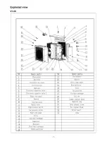
Page 10: ...9 Exploded view V1 08...
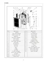
Page 11: ...10 V1 13...
Page 12: ...11 V1 18 23...
Page 13: ...12 V1 28 35...
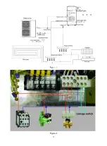
Page 16: ...15 Figure 2 Figure 3...
Page 18: ...17 Figure 7 Figure 8...
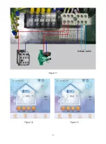
Page 20: ...19 Figure 11 Figure 12 Figure 13...
Page 23: ...22 Electrical Wiring Diagram 1 Single phase system V1 08...
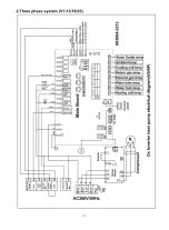
Page 24: ...23 2 Three phase system V1 13 18 23...


