- 6 -
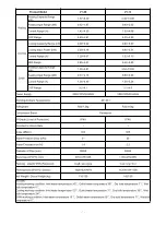
Product Model
V1-18
V1-23
V1-28
V1-35
Heating
Heating Capacity Range
(kW)
5.9~18.2
7.5~23.0
10.2~28.0
12.8~35.0
Heating Input Range (kW)
1.20~4.11
1.53~5.23
2.07~6.36
2.61~7.99
Current Range (A)
1.86~6.37
2.37~8.11
3.70~11.4
4.67~14.3
COP Range
4.43~4.92
4.40~4.90
4.40~4.92
4.38~4.90
Cooling
Cooling Capacity Range (kW)
3.81~11.53
4.73~14.6
6.54~19.8
8.13~24.6
Cooling Input Power (kW)
1.11~4.05
1.39~5.14
1.92~6.97
2.42~8.75
Current Range (A)
1.72~6.28
2.16~7.97
3.43~12.5
4.33~15.6
EER Range
2.85~3.43
2.84~3.40
2.84~3.40
2.81~3.36
DHW
Heating Capacity Range
(kW)
4.80~14.72
6.1~18.5
12.3~20.4
13.6~22.6
Heating Input Range (kW)
1.17~4.60
1.53~5.97
2.8~5.37
3.09~5.95
Current Range (A)
1.82~7.15
2.37~9.26
5.0~9.6
5.52~10.6
COP Range
3.2~4.1
3.1~4.0
3.8~4.4
3.8~4.4
Power Supply
380V/3Ph/50-60Hz
Working Ambient Temperature
-30~43
℃
Refrigerant
R32/2.7kg
R32/2.7kg
R32/3.0kg
R32/3.3kg
Compressor Brand
Panasonic
IP Grade (Level of Protection)
IPX4
IPX4
IPX4
IPX4
Anti-electric Shock Rate
I
I
I
I
Noise (dB(A))
≤57
≤58
≤62
≤66
Water Pressure Drop (kPa)
35
45
40
45
Water Circulation (m³/H)
3.1
4.0
4.8
6.0
Diameter of Pipe (mm)
DN25
DN25
DN32
DN32
Body Size (W*D*H) (mm)
1050×480×1330
1050×480×1330
1160×500×1580
1160×500×1580
Packing size(W*D*H)(Polywood)
1120×530×1470
1120×530×1470
1230
×
540
×
1720
1230
×
540
×
1720
Packing Size (W*D*H) (Carton)
1100×530×1470
1100×530×1470
1200
×
540
×
1720
1200
×
540
×
1720
Net Weight / Gross Weight (kg)
170/180
180/190
210/220
230/240
Remark:
Heating working condition: Inlet water temperature 30
℃
, Outlet water temperature 35
℃
, Dry bulb temperature 7
℃
, Wet
bulb temperature 6
℃
.
Cooling working condition: Inlet water temperature 12
℃
, Outlet water temperature 7
℃
, Dry bulb temperature 35
℃
, Wet
bulb temperature 24
℃
.
DHW working condition: Inlet water temperature 15
℃
, Outlet water temperature 55
℃
, Dry bulb temperature 7
℃
, Wet bulb
temperature 6
℃
.
Note:
The above design and specifications are subject to change without prior notice for product improvement.
Detailed specifications of the units please refer to nameplate on the units.
Summary of Contents for V1 Series
Page 9: ...8 V1 18 V1 23 V1 28 V1 35...
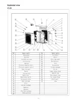
Page 10: ...9 Exploded view V1 08...
Page 11: ...10 V1 13...
Page 12: ...11 V1 18 23...
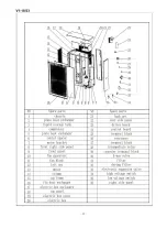
Page 13: ...12 V1 28 35...
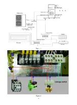
Page 16: ...15 Figure 2 Figure 3...
Page 18: ...17 Figure 7 Figure 8...
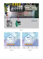
Page 20: ...19 Figure 11 Figure 12 Figure 13...
Page 23: ...22 Electrical Wiring Diagram 1 Single phase system V1 08...
Page 24: ...23 2 Three phase system V1 13 18 23...

