- 4 -
4. No potential danger of any inflammable, gas poisoning, explosion, fire, electrical shock which are
associated with other heating systems.
5. A digital controller is incorporated to maintain the desired water temp..
6. Long-life and corrosion resistant composite cabinet stands up to severe climates.
7. American Copeland compressor ensures outstanding performance, ultra energy efficiency,
durability and quiet operation.
8. Self-diagnostic control panel monitors and troubleshoots heat pump operations to ensure safe
and reliable operation.
9. Intelligent digital controller with friendly user interface and blue LED back light.
10. Separate isolated electrical compartment prevents internal corrosion and extends heat pump
life.
11. The heat pump can operate down to ambient air temp. of -30
℃
。
Section 2
Installation
The following general information describes how to install the EVI DC Inverter air source heat
pump.
Note:
Before installing this product, read and follow all warning notices and instructions.
Only a qualified service person should install the heat pump.
Materials Needed for Installation
The following items are needed and are to be supplied by the installer for all heat pump
installations:
1. Plumbing fittings.
2. Level surface for proper drainage.
3. Ensure that a suitable electrical supply line is provided. See the rating plate on the heat pump
for electrical specifications. Please take a note of the specified current rating. No junction box is
needed at the heat pump; Connections are made inside of the heat pump electrical
compartment. Conduit may be attached directly to the heat pump jacket.
4. It is advised to use PVC conduit for the electrical supply line.
5. Use a booster pump for pumping water in case of low water pressure.
6. A filter on the water inlet is needed.
7. The plumbing should be insulated to reduce its heat loss.
Note:
We recommend installing shut-off valves on the inlet and outlet water connections for ease of
serviceability.
Summary of Contents for V1 Series
Page 9: ...8 V1 18 V1 23 V1 28 V1 35...
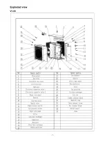
Page 10: ...9 Exploded view V1 08...
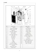
Page 11: ...10 V1 13...
Page 12: ...11 V1 18 23...
Page 13: ...12 V1 28 35...
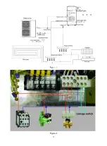
Page 16: ...15 Figure 2 Figure 3...
Page 18: ...17 Figure 7 Figure 8...
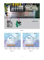
Page 20: ...19 Figure 11 Figure 12 Figure 13...
Page 23: ...22 Electrical Wiring Diagram 1 Single phase system V1 08...
Page 24: ...23 2 Three phase system V1 13 18 23...

