- 16 -
Figure 4
Figure 5
Figure 6
2. For only hot water installation
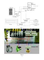
1) System installation diagram to see Figure 7.
2) Electrical wiring diagram to see Figure 8. (If do not need to install auxiliary heating, DO not
connect point 1,4 AC contactor)
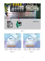
3) Controller panel setting to see Figure 9 .
4) Terminal of 3-way valve is no need for wiring.
5) The head of circulation pump should be big enough. Its actual water flow cannot be less than
water flow on nameplate .
Summary of Contents for V1 Series
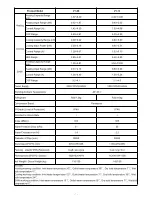
Page 9: ...8 V1 18 V1 23 V1 28 V1 35...
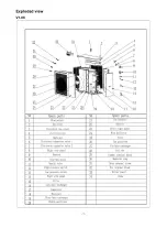
Page 10: ...9 Exploded view V1 08...
Page 11: ...10 V1 13...
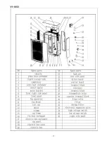
Page 12: ...11 V1 18 23...
Page 13: ...12 V1 28 35...
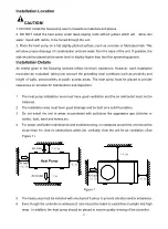
Page 16: ...15 Figure 2 Figure 3...
Page 18: ...17 Figure 7 Figure 8...
Page 20: ...19 Figure 11 Figure 12 Figure 13...
Page 23: ...22 Electrical Wiring Diagram 1 Single phase system V1 08...
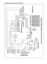
Page 24: ...23 2 Three phase system V1 13 18 23...


