- 39 -
Owner Inspection
We recommend that inspections on heat pumps are done frequently, especially after abnormal
weather conditions. The following basic guidelines are suggested for your inspection:
1. Make sure the front of the unit is accessible for future service.
2. Keep the top and surrounding areas of the heat pump clear of all debris.
3. Keep all plants and shrubs trimmed and away from the heat pump especially the area
above the fan.
4. Keep lawn sprinklers from spraying on the heat pump to prevent corrosion and
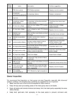
Error
Code
name
description
Solution suggestion
1
IPM Over-current
IPM Module problem
Replace inverter module
2
compressor
synchronous abnormal Compressor failure
Replace compressor
4
reserved
--
--
8
compressor output
phase absent
Compressor wiring disconnected
or poor contact
Checking compressor input
circuit
16
DC bus low voltage
Input too low voltage, PFC module
failure,
Inspect the input voltage,
replace module
32
DC bus high voltage
Input voltage too high, PFC Module
failure
Replace inverter module
64
Radiator over
temperature
Main unit fan motor failure, air duct
blockage
Inspect fan motor, air duct
128
Radiator temperature
error
Radiator sensor short circuit or
open circuit fault
Replace inverter module
257
communication failure
Inverter module doesn’t receive
order from main controller
Inspect the communication
wiring= between main
controller and inverter module
258
AC Input phase absent Input phase absent (Three phase
module is effective)
Inspection input circuit
260
AC Input over-current
Input three phase imbalance (three
phase module is effective)
Inspection input three phase
phase voltage
264
AC Input low voltage
Input low voltage
Inspect input voltage
272
Compressor High
pressure failure
Compressor high pressure failure
(reserved)
288
IPM too high
temperature
Main unit fan motor failure, air duct
blocked
Inspect fan motor and air duct
320
Compressor peak
current too high
Compressor line current too high,
the driver program doesn’t match
with compressor
Replace inverter module
384
PFC module
over-temperature
PFC Module too high temperature
Summary of Contents for V1 Series
Page 9: ...8 V1 18 V1 23 V1 28 V1 35...
Page 10: ...9 Exploded view V1 08...
Page 11: ...10 V1 13...
Page 12: ...11 V1 18 23...
Page 13: ...12 V1 28 35...
Page 16: ...15 Figure 2 Figure 3...
Page 18: ...17 Figure 7 Figure 8...
Page 20: ...19 Figure 11 Figure 12 Figure 13...
Page 23: ...22 Electrical Wiring Diagram 1 Single phase system V1 08...
Page 24: ...23 2 Three phase system V1 13 18 23...


