- 33 -
P16
Ambient temp. for defrosting
0
℃
~20
℃
17
℃
P17
High temperature disinfection cycle
days
0~30 days
Disinfection function is not
executed when set to 0
7
P18
High temperature disinfection start time
0~23:00
23
P19
High temperature disinfection sustaining
time
0~90min
30
P20
High temperature disinfection setting
temperature
0~90
℃
70
℃
P21
Heat pump’s setting temperature for
high temperature disinfection
40~60
℃
53
℃
Celsius/Fahrenheit switch
0 Celsius/1 Fahrenheit
0
P22
Heating target temperature automatic
adjustment enable
0~1 (0 is not enabled, 1 is
enabled) (only applicable
at heating mode)
0
P23
Heating compensation temperature
point
(ambient temperature)
0-40
20
P24
Target temperature compensation
coefficient
1~30 (1 corresponds to
actual 0.1)
1
P25
Compressor’s Frequency operation
mode after constant Temperature
0-Decrease
Frequency
after constant Temp.
/1-Non
Decrease
Frequency after constant
Temp.
0
P26
Pipeline E-Heater Enable Ambient
Temp.
-20-20
℃
0
P27
Water Tank E-Heater Entry time
0-60 min
30
Language
0-English/1-Polish
0
F01
Heat Pump Function
1 Heatng only
2 Cooling
3 Hot water
4 All three
4
F02
Circulation pump status after
reaching target temp.
0 intermittently open
1 always open
2 constant temperature stop
1
F03
Circulation pump on-off cycle after
reaching set temp.
1~120min
30
(
30min off,
3min on
)
F04
DC circulation pump mode
0 Not enabled
1 automatic
2 Manually
1
F06
DC water pump manual speed
10~100%
50
F08
Minimum speed of DC circulation
pump
10~100%
40
High Temperature Antisepsis Function: (when hot water function is selected)
◎
High temperature Antisepsis cycle is once every 7 (P17) days;
◎
When entering the high temperature Antisepsis, the water tank electric heater will be
Summary of Contents for V1 Series
Page 9: ...8 V1 18 V1 23 V1 28 V1 35...
Page 10: ...9 Exploded view V1 08...
Page 11: ...10 V1 13...
Page 12: ...11 V1 18 23...
Page 13: ...12 V1 28 35...
Page 16: ...15 Figure 2 Figure 3...
Page 18: ...17 Figure 7 Figure 8...
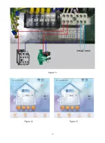
Page 20: ...19 Figure 11 Figure 12 Figure 13...
Page 23: ...22 Electrical Wiring Diagram 1 Single phase system V1 08...
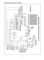
Page 24: ...23 2 Three phase system V1 13 18 23...


